Using Sculpt to Deform, Distort, or Age Meshes
Making something look ‘old’, ‘used’ or displaying appropriate levels of wear-and-tear, can be one of the more difficult aspects of 3D to master, often because such ‘ageing’ needs to appear natural and relatively random, albeit subject to the forces of physics, like an old house falling to bits under its own weight. Normally this would mean having to carry out quite extensive work in edit mode, pushing and pulling vertices, edges and faces to bring about a desired look which is often unsatisfactory, if a little forced or contrived. Fortunately, Blender’s “Sculpt Mode” tool comes in handy in this regard as an intuitive, and relatively quick alternative to manual mesh editing.
A basic understanding of Blender is required to get the most from the following material. The basic principle and most operations can be used in various versions of Blender but will need to be checked beforehand as they are not available in all (very early and/or later experimental iterations in particular).
Preparing the mesh in Blender
Before actually doing anything to the mesh it’s best to be mindful of two main issues;
- Vertex, polygon & edge loop distribution
Making sure there are enough polygons and ‘edge loops’ present to allow the mesh to deform problem free. - Coincidental position of vertexes
The results of deformation won’t always work the way its expected when elements are not aligned correctly.
What both of these mean is that where ever possible the mesh should be built in a ‘optimised’ fashion for editing rather than for it’s use in a game engine, there is a difference. Optimising for editing means the mesh is constructed in such a way as to allow for easy manipulation and changes to the object, it should be relatively easy to add or remove details on such a mesh. On the other hand, a model optimised for game/interactive media use is usually stripped right down to its essential elements, which often mean that further editing can be difficult due to having to work around the often limited shapes and numbers of polygons a model contains (usually triangles’ which further complicate additional editing). Bear this in mind when doing the initial build work on the modeled object, game optimisation can come later.
Vertex, polygon & edge loop distribution
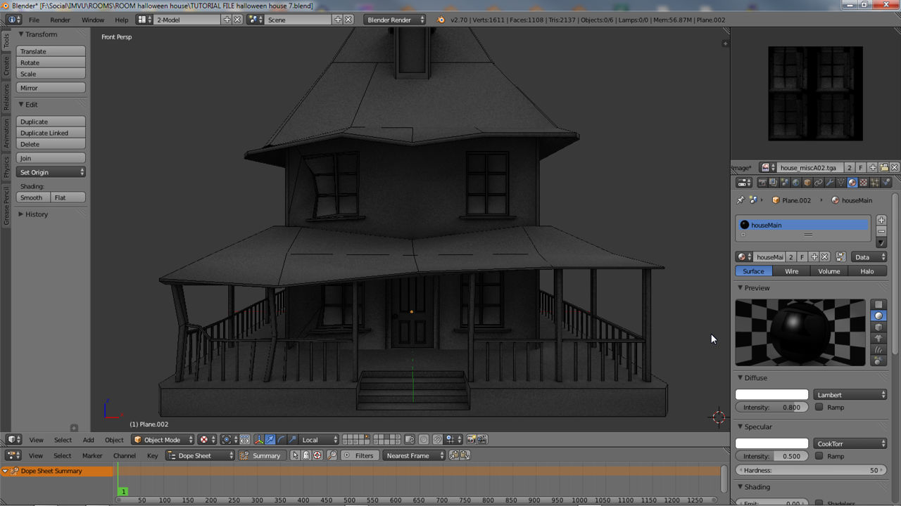
As mentioned above it’s important to keep in mind when building a model the eventual goal in terms of what is going to be done with the mesh physically and not just what its going to look like rendered in game. What this means is that as a mesh is constructed, vertex, face and edge loop distribution has to take into account any eventual mesh deformation; it’s no good adding a subdivision to the roof of a building, for example, without adding a complimentary division in a lower wall, preventing gaps from appearing where faces don’t meet up. The image below shows this by way of a series of ‘edge loops’ that travel down the building from top to bottom; because the loops do this, manipulating the area between roof and wall will result in uniform distortion between the two sections.

Making sure that ‘edge loops’ follow the contours of the mesh which will allow for better deformation
Snap: coincidental vertexes
The results of deforming don’t always go as planned, especially where prior care hasn’t been taken to ensure ‘edge loops’ follow the general contours of the mesh (top to bottom, side to side). What this means is that edges, and more importantly vertexes comprising the different sections of a mesh, need to match up – tracing an edge across sections, a ‘wall’ and ‘roof’ vertex should occupy the same co-ordinates in space where each section follows-on to the next. Not ensuring this is done now (as best as possible) might result in the formation of gap and cracks because of position differences between edges and vertices. This can be done using “Snap“, if vertices are to be co-located – two individual vertices occupying the same location. Or “Merge” if vertices need to be joined together forming a single vertex.
Design note: when needing to ensure vertexes from different mesh are in the same location the following can be done per-section or by temporarily using “Join” to connect everything together – the former tends to be less convenient than the latter, especially when care has not been taken to identify mesh sections using Material assignments (which makes for easier group or mass selections).
Depending upon the version of Blender used, to “Snap” vertices together to form a co-located group; in Edit mode “Shift+RMB” select two or more vertexes, ensuring the last one chosen is the item to which everything is to snap. Once done press “Shift+S” to access “Snap” options and select “Cursor to Active” (or click “Mesh » Snap » Cursor to Active” from the 3D View Header). The cursor will ‘snap’ to the last item selected. Then again, “Shift+S” to open Snap options, this time selecting “Selection to Cursor” (or “Mesh » Snap » Selection to Cursor” from the 3D View Header menu again) to snap all the previously selected elements to the Cursor forming the co-located group comprising individual vertices.
Design note: in Blender 2.45, and possibly earlier versions of Blender, “Selection to Active” is not an available snap option so the Cursor has to be manually repositioned. This can be done by selecting the vertex to which everything will snap, “RMB” select, and from “Snap” options clicking “Cursor to Selection” (“Shift+S : Snap » Cursor to Selected“). Once done the remainder of the process can be followed as per the above. Use “Ctrl+Z” to undo any mistakes and/or try for different results.


“Snap” can be accessed via the “Mesh” menu in the 3D View Header, or using the “Shift+S” shortcut shown in both 2.49 and latest versions of Blender (accessing “Snap” via the Header menu or shortcut displays the same pop-up options)
Merge: joining vertex selections together
Depending on the complexity of the Object needing to be shaped it may be more convenient to “Merge” vertexes together before using Sculpt to prevent, or at least mitigate, the appearance of gaps and cracks where individual vertices might not move as a group when selected and manipulated. This differs from “Snap” in that selections are physically joined together to form a single selectable element – one vertex rather than many in the same place.
Design note: being in “Wire” display tends to mitigate group manipulation problems as a result of “Drill-Down” selection – being able to select several vertices occupying the same location that might not otherwise be selectable.
Similar to the “Snap” process above, using “Shift+RMB“, select two or more vertexes and then press “Alt+M” to access “Merge” options (or select “Mesh » Vertices » Merge” from the 3D View Header). From the list select the option representing the outcome needed – “At First” merges everything in the selection to the first or initial vertex selected; “At Last” merges everything to the last selected vertex, and so on.
Design note: when making selections it’s important to observe the order in which the selection is made so it results in a given element being the item to which everything will be subsequently joined. Use “Ctrl+Z” to undo any mistakes and/or try out different results. Making sure vertices are in the same place beforehand also reduces the extra work that may need doing to the UVW map after distorting the mesh with the sculpt tool or moving vertices around.


Using “Merge” options allows individual vertices selected as a group to be joined into a single instance. Shown above, in both the latest Blender 2.49, are the menu options and shortcut menu (using the Header menu or shortcut accesses the same options pop-up)

Merging selected vertices together at their collective mid-point. Other options allow for different merge points – first, last, etc.
Joining meshes
As briefly mentioned above, although it is possible to use the Sculpt tool without necessarily joining meshes and then merging vertices together into a single whole, it often yields better results, and is more practical, to do so, especially on complex or difficult models. This does mean however that it’s important to set up Material assignments properly so they can be used to better aid judicious selection. First, “Join” meshes together.
In Object Mode, using the various selection tools (“A” to select everything in the scene; “Shift+RMB” to individually select etc.), depending on what needs to be connected to what, select the necessary parts, making sure one of the Objects remains the “Active” selection – typically the last item selected – this will be the item to which everything is joined. Once done press “Ctrl+J“. Depending on the Blender version this will either instantly “Join” all the selected meshes together (latest versions), or the “OK?” confirmation pop-up will appear (Blender 2.49 or below) – click “Join selection meshes” to complete the process.


It’s often best to “”Join” Objects together into a single item to ensure it deform properly when using the Sculpt tool. This can be done using “Ctrl+J” to “Join” meshes
Once the meshes are joined together, in Edit mode (“Tab“) select everything, “A“, and click the “Rem Doubles” button located in the “Mesh Tools” properties panel 2.49 or below, or the “Remove Doubles” button in the Tool Shelf on the left-hand side of the 3D View in newer versions of Blender. This instantly merges all co-located vertices together forming a single contiguous mesh (and Object) ready for Sculpt manipulation.
Design note: for newer versions of Blender the Tool shelf has undergone some changes with the introduction of ‘Tabbed’ tool groups, so that although “Remove Doubles” is in the Tool shelf, it may actually reside in a tool sub-group which needs to be selected before accessing the tool button itself.


Once meshes have been Joined it’s best to “Rem Doubles“(“Remove Doubles“), an automated tool for collapsing and merging vertices together within a set tolerance (note that in newer versions of Blender the tool may be located within a ‘Tab’ rather then the generic Tool shelf as previously
Switching to “Sculpt Mode” and basic tools
Once meshes have been joined, vertices merged where needed and Material assignments checked, it’s time to use “Sculpt” mode to modify the mesh. To switch, exit “Edit” mode, “Tab“, if still active and then click the “Mode:” selector in the 3D View Header. From the list select “Sculpt Mode” – the interface and cursor will change, the former to show various ‘sculpt’ related tools, brush settings etc., the latter to include an outline indicating the sculpt tools brush size. Aside from these changes Sculpt mode has a similar appearance to Object and other modes.
Design note: for Blender 2.49 or Below the settings and options for sculpting appear in what is usually the “Transform Properties” panel (“N”), which in sculpt mode is named “Sculpt Properties“. In current versions of Blender more extensive sculpt tools appear in the left-hand Tool shelf”.


Entering “Sculpt” mode, accessed from the “Mode:” selector in the 3D View Header, to begin distorting the mesh after the basic prep has been done


The tools for sculpting will appear either in the Tool shelf on the left when using the latest versions of Blender, or the tool/properties panel, usually reserved for “Transform Properties” (“N“) in 2.49 or below, in addition to to the cursor changing to a circle (indicating the ‘brush’ used to ‘paint’ the mesh)
Using Sculpt
Once Sculpt mode is active, in combination with normal scene manipulation actions, “Shift+MMB” etc., it is then just a matter of using the mouse cursor like a paint brush and click-holding the left mouse button whilst performing ‘paint’ or ‘scribble’ motions as needed across the mesh, similar in many ways to using a 2D paint or image editing program – as the cursor moves across the mesh it deforms to varying degrees based on the tool and their respective properties.
Design note: the efficacy of Sculpt is influenced by two aspects of a Scene; it’s relative ‘scale’ – represented in Blender 2.49 or below as “Spacing:” in “View Properties” , or “Scale” in the “Display” sub-section of “View/Transform Properties” (“N“) in later versions of Blender; and/or the the items relative size and dimensions in the 3D View. Both affect the way the tool works with respect to its ability to deform a mesh – the larger it is, the less movement occurs. This means very large objects may need to be temporarily resized (and ‘fixed’ using “Apply“, “Ctrl+A”) for best results, especially in Blender 2.49 or below, resizing back up once done.
Problems with Sculpt deformation
Despite best efforts it’s not unusual for gaps and cracks to occur in areas where the mesh was not adequately prepared beforehand, for example, after a pass over the hose model shown below the following problems now exist;
- Edge flow and disparity causing gaps between windows and surround.
- Polygons pulled too much out of shape due to being a little heavy handed.
- Gaps caused by not subdividing handrails to take into account mid-point distortion.
- Gaps caused by deforming the porch roof but not the support uprights.
Each of these problems is generally the result of the mesh not being fully contiguous, i.e. everything being connected ideally vertex-to-vertex, which tends to result in the types of uneven deformations indicated. Fortunately these issue can be fixed quite readily in Edit mode though normal mesh editing activities – adding loopcuts (“Ctrl+R“), cutting the mesh (“Ctrl+K“), manipulating vertexes (“G“) etc.

After some mesh distortion using the sculpt tool showing some problems that will occur when using sculpt on a mesh in this way
Tidying up the mesh and checking the UVW maps
Aside from issues that directly effect the mesh structure, depending on how extreme the sculpted distortions are, it may also mean having to check and adjust any UVW and texture mapping for issues, typically stretching, malformation, incorrectly positioning etc. in the “UV/Image Editor“. Whilst it is possible to leave minor problems untouched it is often the case that some adjustments will need to be made especially where unique texturing has been used.
Design note: it’s generally better to unwrap and texture objects beforehand because changes to the mesh often change the ‘character’ of an Object (the way the UVW unwraps itself based upon the items shape and general contours), to the an extent that a minor change to the mesh – one or two vertices being pushed away from their previous locations for example – might result in a completely different unwrap of the UVW when all that might actually be needed is a readjustment of affected vertices in the current UVW map.
Looking at the images below for example, the earmarked areas indicate problems where previously hidden or occluded dark patches of an assigned Ambient Occlusion map (texture) are now visible as a direct result of mesh deformation and various elements being moved from their original locations. In other words, whilst the mesh has changed shape, the layout of UVW map has not accommodated those changes.
Design note: these types of issue need to be addressed manually as Blender can’t track and fix changes to either mesh structures or UVW map layouts automatically – the application cannot make any contextual determination as to why something is being changed and how that then relates to other aspects of the same Object.

Areas of texture distortion as a result of using sculpt to edit the mesh. These usually need correcting.
This means then that UVW maps will need to be redone or at least adjusted to take into account any change that have occurred. The house shown for example now needs to have its Ambient Occlusion maps re-baked now the mesh structure has changed.
Design note: UVW map alignment issues tend to be more noticeable where models have been mapped ‘uniquely’, i.e. each Material assignment contains a single texture that is NOT tiled across a surface; tiled textures typically necessitate a slightly different approach to fixing deformation issues because associated problems may not be as noticeable To work out which is which, or how much work needs to be done to fix UVW map distortion issues, it is always a good idea to have access to a set of ‘grid maps’ – textures that have a simple checker or line based grid covering their surface, making it easier to find and fix problem areas due to the appearance of texture distortion.

Before and after showing area #1 updated after re-baking the ambient occlusion maps.
Once the textures or UVW maps have been readjusted (in addition to being re-baked as the case is here), simply reassigning them back over the mesh will check if the errors remain (show below). Depending upon the amount of change undergone, this process or checking, re-mapping and fixing UVW maps may need to be done several times until issues are fixed.
 are no longer distorted")
Test render on the broken house to check the alignment of the baked Ambient Occlusion maps and whether they are no longer distorted or exposing what should remain black occlusions (areas not exposed to light)
Conclusion
Overall although the type of manipulation afforded by the use of Sculpt can be done with standard manipulation in Edit mode, usually through the assistance of “Proportional Editing” and the different tools options that provides, it’s not generally as intuitive as being able to deform items in a broader context, at the ‘object’ rather than ‘element’ level, that is the Object in it’s entirety rather than elements of it. In saying this however, that is not to suggest that using Sculpt to deform should only be used on it’s own and in isolation of ‘Edit’ based modifications because, as discussed above, the use of both is often necessary.
")

The final fixed version after the mesh has been edited so any open gaps and holes have been closed, UVW maps edited and repaired, and textures re-baked (where necessary if/when using texture baking)

