Make A Simple Animated Snowman In Blender
Modelling a 3D character in Blender is no more difficult than putting together any other type of object. In other words, whilst there are additional considerations, especially if the model is to be animated, overall the same principles and construction techniques are employed as would be used to make a ‘chair‘ or ‘sword‘.
In the following seven part tutorial the process of building a simple low-poly ‘game’ character, a ‘Snowman’, will be shown along side a number of important but infrequently discussed general considerations that need to be kept in mind whilst doing so. From initial scene set-up to modelling and material assignments, on to UVW mapping and texture baking, then finally to ‘rigging‘ the mesh for articulation through the use of an Armature, and creation of two simple animation sequences.
Although not an absolute necessity, it is recommended the ‘making a simple chair‘ and/or ‘making a simple sword‘ tutorials be done beforehand, or at the very least a basic understanding of using Blender be had.
Download: KatsBits – Snowman Character Source (c. 40 MB | *.blend, *.tga, *.psd, *.xcf). Zip file includes each stage of the process as indicated throughout.
Important: the following tutorial is ‘agnostic’ in that the principles and techniques explained throughout are core to most versions of Blender post 2.50, up to and including the latest release.
Getting started & concept
The actual process of making an animated game character (or any type of animated object) can broken down into three main stages; 1) the mesh is constructed, UVW mapped and textured; 2) the resulting model is given an skeleton and ‘rigged’ for use as an animated object; and finally 3) using the skeleton and rigging, the mesh is deformed and articulated through a series of ‘poses’ which constitute an animated sequence. For the ‘Snowman’ character belonging to this tutorial this means first it will be built, then rigged, and finally two simple animation sequences made.
So to begin. The first step is to find a ‘concept’ image(s). This can be as simple as a sketch drawn on a piece of paper or doodle on a napkin, to paintings, photographs or movies, anything in fact which provides a starting point for inspiration, and/or/both, can be used in a way that guides the development of a meshes general characteristics. It’s important to note that although concepts are not an absolute necessity, it’s usually a good idea, and good practice, to have something of this nature to hand as they tend to make the entire process less nebulous and more directed (prevents the artist being side-tracked too easily by ideas that offshoot during production).
Design note: be mindful that more complex concepts may result in there being less latitude for interpretation, so long as a basic idea is clearly described visually, even a basic sketch should be sufficient. The doodle below is a case in point, scribbled as it was in a notepad, the basic shapes and forms provide a general overview of the characters ‘look’ without necessarily binding the artist to the details. Additionally, so long as concepts are in a form which is readily available they can be in or on any medium – it is not necessary they be high-resolution digital paintings.

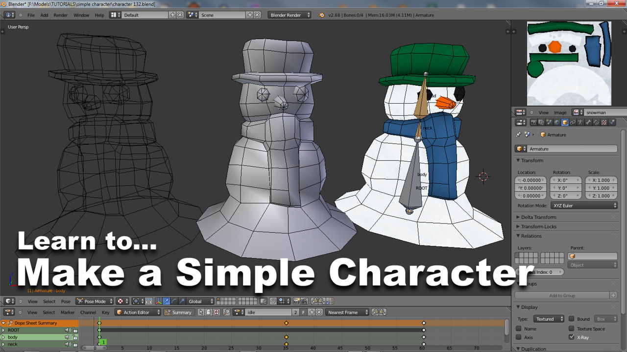
Overview of the project upon completion; a simple textured mesh, a basic ‘rig’ (Armature) and two simple animation sequences (only one shown)

Very simple ‘concept’ of the Snowman character to be modelled. It’s not entirely necessary that a concept be a form of ‘high art’; so long as the general ‘intent‘ is clear then a few scribbles (doodle) in a notebook are more than adequate, as is the case here
Scene scale and Unit size
Before making a start on the modelling process, be sure to be using a ‘clean’ scene. So either restart or reload Blender, or with the application open, from the “File” menu click “New” to wipe the current file, replacing it with a brand new workspace. The reason for doing this is two-fold, 1) from a practical point of view it simply prevents old data being trapped in the new project when the file is saved. And 2) a number of essential “Properties” which relate to the scene and objects contained therein ideally need to be ‘reset’ to defaults. This latter aspect is especially important because it’s used to determine a ‘global’ relationship between Blender and environments outside the application (other game development tools). This is generally done through the use of two primary settings; the scenes “Scale“, which defaults to “1.000“; and its “Unit” of measurement, which defaults to “None“.
In essence what this means is that before any polygons are split or faces moved, the relationship between ‘model’ and ‘scene’ may need to be changed relative to what the mesh is to being made for and where it’s going to be used. In other words, because it’s quite typical for interactive technologies to use proprietary scaling, “Scale” and “Unit” properties should be set so the resulting model fits the environment into which it would eventually be placed.
Design note: the “Scale” and “Unit” properties of a Scene should be determined beforehand by looking into the requirements of the engine being used; although this is not necessary for the following tutorial, it is important to be aware of and understand nonetheless – trying to change these aspects of the process after-the-fact can be problematic, so it’s best to set them up correctly from the start. For more detailed information on Units of Measurement in Blender click here.

How object size relates to different game development tools. Whilst “Scale” and “Unit” sub-systems can be set to match a particular environment, the objects are not automatically rescaled to match. This means meshes may need to be physically scaled to match requirements
To set the appropriate options, with the mouse over the 3DView, press “N” to access the “View/Transform” properties ToolShelf. Scroll down to “Display” and in that sub-section change “Scale: 1.000” to an appropriate value (e.g. “8.000” for ‘idtech/UDK’, or left at default “1.000” for ‘Unity’). To switch the measurement system from “None“, in the main “Properties” panel on the right, click the “Scene” button (second icon on the left), and in the “Units” sub-section click either “Metric” or “Imperial” as per requirements.
Design note: generally speaking the final arbiter of size relates to how something looks on screen rather than its dimensional accuracy. This is because the camera through which a world is observed, has a tendency to distort both field of vision and an objects proportions due to perspective.

Setting “Unit“[2] of measurement from “Scene” properties and a general “Scale“[1] value from “Transform/View” properties. Both are important settings to consider when making content that’s to be used outside Blender as it’s likely the destination application won’t match the Blenders default units of measurement
Scene view controls
Before doing any mesh editing it’s generally preferable to switch between “Perspective” and “Orthogonal” views so any subsequent additions to the scene are viewed, initially, without the distorting effects typically associated with representing three-dimensional objects on-screen. In other words, in the absence of perspective, objects appear ‘flat’. The difference between the two view types is important to understand because using perspective can make objects and object relationships tricky to assess under certain circumstance.
Design note: being familiar with this function, either through the use of shortcut keys or menu options (below), is essential for an efficient use of Blender; its a core member of a tool group that controls the way a scene and objects contained therein are displayed and manipulated.
To toggle between each view, with the mouse over the 3DView press “numPad5” to switch from “Perspective” to “Orthogonal” view (or using the “View” menu in the 3DView Header click “View » View Persp/Ortho“), and then into one of either “Front“, “numPad1“, or “Right“, “numPad3” view (or again from the 3DView Header, “View » Front” or “View » Right” respectively). This changes the scenes orientation so the default cube object (and scene generally) is seen ‘side‘ or ‘front‘ on.
Design note: view orientation controls, commands or shortcuts tend to either ‘toggle’ behaviour (turn it on/off), or switch it with another selected view type (changes to the view associated with the specific actuator).

All models usually start from the default scene, although not necessarily using the default cube object which sits within [blend1]
With the scene displayed without perspective, reposition the default cube using “Shift+MMB” to “Strafe” (“left/right”, “up/down”) and/or use “Ctrl+MMB” or “MMB+Scroll” to “Zoom” (“in/out”) the scene so there’s enough room above the cube to fit another similarly sized object.
Design note: although ‘flattening’ the scene is not an absolute necessity, because full perspective can makes objects appear distorted, Orthogonal view often helps better assess relative shapes and sizes.

Using the default cube as a guide, the scene is positioned so there’s room to add, manage or manipulate multiple objects in the scene – the ‘head’ of the simple Snowman character can be placed in the space above the cube
Setting the cursor
Once the scene has been arranged, and before moving on to modelling, the location of the “3D Cursor” needs to be checked. As new additions to the scene are placed at the cursors location, it’s good practice to make sure it’s initially positioned at ‘grid centre‘. There are two ways the cursor can be relocated; one relies on the fact that a centred object already exists in the scene – the default cube; the other makes use of a set of coordinates. Both approaches have a direct effect on the cursor.
Design note: because the cursor can be placed anywhere and at any depth relative to the screen, it means new inclusions will be similarly positioned, potentially making them difficult to locate. For game related content this is especially important, because grid-centre is often used as the basis around which a mesh develops, either as a general ‘centre of mass‘ reference, or as an actual ‘origin point‘ which can be used to ‘ground’ or ‘root’ a model later on.
To use the cube, RMB select it and press “Shift+S” to open the “Snap” menu, from the available options select “Cursor to Selected” – if the cursor is not already in that position it will ‘snap’ to the cube and its “Origin Point“. To use coordinates/manually set the cursors location, with the mouse over the 3DView, press “N” to open the “View/Transform” properties panel (if not already visible) and scroll to the “3D Cursor” sub-section. Here find the sub-property called “Location:” and make sure or change the “X:“, “Y:” and “Z:” values to “0.000” – the cursor will move to the new location. In both instances, snapping to the cube or manually setting coordinate values, it is now at “grid centre” or “0,0,0“.
Design note: the “Origin Point” (“Point of Origin“) is the small orange coloured feature (spherical dot) the Transform Widget focuses on when selecting meshes in Object mode; although by default it’s located ‘centre of mass’, it can be reset and repositioned anywhere.

Before placing additional objects in the scene ideally the cursor should be centred correctly to the grid using “Shift+S” to prevent issues further into the process, especially whenever animated objects are involved

Alternatively, using “3D Cursor” coordinates via “Transform Properties“, ‘zero’ out the “X:“, “Y:” and “Z:” values to manually place the cursor correctly [blend3]
Switching Viewport Shading
When working in Blender it’s often useful to be able to change the way an object or objects are displayed in the 3DView. “Viewport Shading” as this is called, determines how a scene renders its contents based on one of four available options; “Bounding Box” – renders objects as simple boxes based on the amount of area they occupy; “Wireframe” – displays the underlying structure of an object, the ‘scaffolding’ in a manner of speaking; “Solid” – renders objects as solid forms the colour of which can be tinted; and “Texture” – displays images mapped to the object. So for example, ‘Wireframe’ reveals the structure of a mesh, how the polygons flow around the object, very useful to see how edits effect not only the immediate area, but also how those changes work in relation to the overall distribution of surfaces. Using ‘Texture’ mode can be used to not only show the object with assigned textures, but also how and where the images are ‘mapped’, whether there are any distortions, poor areas of distribution and so on (these aspects of using Viewport Shading will be discussed to follow).
Design note: “Bounding Box” is not typically used as often as the Solid, Texture or Wireframe, but can be useful when a scene contains a large number of individual items. Note also that “Solid” is the default shading option (objects are tinted a mid-grey tone where materials are not present or their ‘colour’ not yet set) and that “Solid” and “Texture” shading are affected by scene lighting.
To toggle back-and-forth between modes use the “Viewport Shading” menu in the 3DView Header – click the button with the spherical icon and select the appropriate option – “Bounding Box“, “WireFrame“, “Solid” or “Texture“. Or use a keyboard shortcut; “Alt+Z” toggles between “Solid <-> Texture“, “Z” toggling “Wireframe <-> Solid“. To ‘jump’ between “Wireframe <-> Texture” first press “Z” followed by “Alt+Z” (or press “Alt+Z” twice); and from “Texture -> Wireframe” simply use “Z“. As with “Perspective” and “Orthogonal” display, “Viewport Shading” is another essential tool for efficient use of Blender.
Design note: although switching ‘up‘ from “Wireframe” to “Texture” mode requires “Z” followed by “Alt+Z” or “Alt+Z” twice (because mode changes are passing through another option), going the other way, ‘down‘ from “Texture” to “Wireframe“, only requires “Z” be pressed once. This means that certain mode changes are ‘expressed’ (done quickly) due to their bypassing intermediary display states (usually “Solid” mode).

Toggle into “Wireframe” using the Header menu option or pressing “Z“; this simple action helps to see the underlying structure of the objects as they are put together – it’s typical to toggle between the different “Viewport Shading” options whilst making something as each provides the users with different visual cues as to what is being seen and the relationships between objects in terms of their structure and general appearance
Adding Objects to the scene
Starting with the default scene the elements from which the character is to be made can now be added. As the Snowman will be ostensibly ’round’ in general appearance it makes sense to begin the process using similarly shaped meshes, in this instance “UV Sphere” objects.
Design note: UV Sphere objects belong to a group of meshes commonly referred to as “Mesh Primitives“. Alongside “Cube“, “Circle“, “Cone” and others simple shapes, they form the fundamental building blocks from which most modelling projects start life. Note that using the word “simple” in this context refers to an objects appearance rather than its internal complexity, i.e. the number of polygons it contains – generally speaking each Primitive uses a differing numbers of polygons depending on the items structure; curved surfaces have the most, a property that can be adjusted once an object is loaded into a scene.
To load an object in to the scene, with the mouse over the 3DView press “Shift+A” to access the “Add” menu. Once open select “Mesh” then “UV Sphere” from the list of options (alternatively from the ‘master’ Header [screen top] click “Add » Mesh » UV Sphere“); a spherical object will appear at the cursors location and a set of properties will become available in the ToolShelf on the left (the ToolShelf should be visible by default, if not, press “T“).
Design note: when Objects are added to a scene they are automatically selection highlighted, i.e. ‘active’, and any initial property values are made available for editing. Remember that objects are ‘spawned’ at the cursors location, which is why it’s important to check and reset it’s position beforehand.

Leaving the default cube in place (as a reference), “Shift+A” to access the “Add” menu and add an “UV Sphere” – the object will centre itself to the cursor (which is why it’s important to reposition it)
Editing an Objects initial properties
Upon being added to the scene the initial state of the sphere is that of a relatively dense mesh, i.e. it contains a large number of horizontal and vertical subdivisions. Whilst this makes the object appear smooth, it does so at the expense of using a tremendous number of individual faces. For low-poly game related work this is not ideal and needs to be moderated by adjusting the aforementioned horizontal and vertical subdivisions via the objects initial property settings.
Design note: modifying the initial settings attributed to an object and mesh editing are two distinct processes, the former cannot be accomplished once the latter has begun. As a result, it’s recommended alterations be done immediately upon adding objects.
To do this, looking at the ToolShelf once the sphere has been added (press “T” if not visible), a new section, “Add UV Sphere“, will appear at the very bottom. In this sub-section is a “Segments” sub-property, click the left arrow to change the value from “32” down to “12” (or click the number to highlight, type “12“, then press “Enter“). Similarly lower “Rings” to “8” down from “16” – the mesh will either live-update, or change after values have been entered, resulting in the sphere appearing in the 3DView with fewer individual faces and horizontal and vertical sub-divisions, making it ready for editing.
Design note: if the objects properties are no longer available or visible in the ToolShelf press “F6” to access the “Add…” dialogue overlay to make the necessary changes. If nothing appears when doing this it means something has changed the Objects ‘state’ such that properties can no longer be accessed or changed. In such instances the item will need to be deleted, “Del” and a new instances added back into the then empty scene. The options available will vary depending on the object selected.

The default sphere is a relatively dense object which generally needs to be reduce from its default 32 “Segments” and 16 “Rings” – this is too dense for the type of low-poly game related modelling being done here [blend3b]

An Object initial properties can also be accessed pressing “F6”. If this does not appear it means the current item will need to be removed and a new instance loaded into the scene

Using the “Add UV Sphere” ToolShelf options bottom-left, change “Segments” to “12” and “Rings” to “8” – “Size” can be left as-is – this reduces the sphere internal complexity making it better suited for low-poly work [blend4]

The new sphere in “Perspective” mode, shown just to provide a sense of its shape relative to the default cube object [blend4b]
Object duplication
The quickest or most convenient way place additional objects in the scene is to simply copy ones that already exists. However, the typical ‘copy/paste’ approach to doing this does not work on mesh objects in the 3DView because it’s a ‘context-sensitive‘ operation. Instead “Duplicate” has to be used.
Design note: the availability of “context-sensitive” actions is dependant upon the type of object selected, the activity being carried out, and where it is being done (the window or view over which the mouse is active).
There are two main types of mesh object duplication; 1) “Duplicate” and 2) “Duplicate Linked“. The former, “Duplicate“, produces individualised objects that can be edited independently of other instances (the original or duplicate/s). The latter, “Duplicate Linked“, produces a ‘linked’ copy of an original, meaning, any subsequent changes to either the original or copy immediately propagate across all, removing the need to manually update each separately. As the entire character needs to be editable, “Duplicate” is the better option of the two to use.
Design note: similar to other functions in Blender, ‘Duplicate’ and ‘Duplicate Linked’ can be accessed using keyboard shortcuts or from an ‘Header’ menu option, in this instance “Object“. To use “Duplicate” press “Shift+D” or used the 3DView Header menu option “Object » Duplicate“. For “Duplicate Linked” the shortcut is “Alt+D“, the menu option “Object » Duplicate Linked“.
To create a duplicate, RMB select the sphere and press “Shift+D“. A new instance of the original will appear. RMB click to confirm and release the object. Upon doing this it will snap back to a default location, generally the same coordinates as the original mesh.
Design note: when the duplication appears it’s ‘attached’ to the mouse so it moves when the mouse moves. This generally serves two purposes; 1) it’s an obvious indicator that an object has been duplicated; and 2) the object is active and ready to be moved in a single action (rather than it having to be selected and then moved, two separate actions in sequence). Because Blender does this (pairs object and mouse together directly after duplication) it does mean the item can be inadvertently repositioned by accidentally using LMB, which sets the object at the cursors location, instead of RMB, which just confirms duplication. If/when this happens, delete the duplicate, “Del“, and try again paying particular attention to using RMB. The difference between using LMB and RMB here is another “context-sensitive” issue to be aware of (using “Ctrl+Z” to “Undo” will remove the object rather than just ‘undoing’ the accidental placement).

The character makes use of two spherical shapes, use “Shift+D” to “Duplicate” the first sphere – RMB click to confirm and release the new object [blend4c]
Basic Object manipulation
With two spheres now in the scene they can be used to ‘block out’ the characters basic structure by placing one atop the other. This is done using the “3D Manipulator Widget” or a “Transform” action.
Design note: because both objects occupy the same location, RMB clicking as outlined below, will make an either/or selection, it doesn’t matter which is selected because the objects are identical.
To position the mesh do one of the following. First RMB select the object so the “3D Manipulator Widget” appears, then either; 1) LMB+hold+drag the widgets blue handle, moving the sphere upwards so it’s positioned atop the lower of the pair. LMB release the mouse to set the new location. 2) press “G” then “Z” to “Grab/Move” the object whilst locking it to the “Z” axis (up/down). Move the sphere atop the lower of the pair then LMB click to confirm. Or 3) RMB+hold+drag to select and move the sphere using a single action. Move above, then LMB click to set the new location. Whilst doing any of the above holding down the “Ctrl” key after the action has been initiated will snap movement to the grid.
Design note: there is a distinct advantage in using the shortcut (“2”) and/or RMB+drag (“3”) to move objects around because when doing so using the widget (“1”), the action cannot be cancelled midway through the process; object manipulations have to be set in place first and then undone (“Ctrl+Z“). On the other hand, both the shortcut and/or RMB+drag are actions can be cancelled simply by using RMB at any point. In both instances this will reset an object(s) back to its original pre-transform position. Also note, the “3D Manipulator Widget” defaults to “Translate“, the shortcut key for which is “G“. Alternatively from the 3DView Header, select “Object » Transform » Grab/Move” or click the “Translate manipulator mode” icon in the widget control section (shown below).

Selecting an object highlights the “Manipulator Widget” which can be used to “Translate” (shown), “Rotate” or “Scale” objects in and around the scene – objects can be moved directly using the widgets directional “X“, “Y“, or “Z” handles (or the centralised ‘global’ area), or using different shortcut keys (“G“, “R” or “S“)

Moving one of the spheres above the other should result in something similar to the above – note that the overlap will be important later on so should be present upon completing this action – this simple ‘block out’ provide an initial idea of shape and form (even though it’s to be adjusted later) [blend5]
Once positioned the sphere needs to be resized approximately 25% smaller using “Scale“; this is to be the characters head – the end result being a smaller sphere on top of a slightly larger one.
Design note: when originally positioning the sphere, a certain degree of overlap will be necessary to compensate for the scaling, this can be adjusted afterwards if necessary.
To do this, make sure the (upper) object is selected, RMB, and press “S” to initiate “Scale” (alternatively in the 3DView Header activate “Scale manipulator mode” by clicking the ‘Scale’ widget icon, or from the “Object” menu select “Object » Transform » Scale“), move the mouse towards the objects centre a short distance to reduce it’s size – pressing “Ctrl” after initialising the action will snap scaling to increments making a regulated resize easier to do. LMB click to confirm.
Design note: when using ‘Scale’ make sure the mouse cursor is a reasonable distance from the object before initiating as the speed and sensitivity of the tool is dependant upon this; the closer to object centre, the faster (and seemingly uncontrollable) movement may become.

Scaling objects (resizing them) can be done using the shortcut, “S“, or by activating “Scale manipulator mode” from the widget control block in the 3DView Header. (Note using any widget mode is subject to the same caveat with respect to canceling an action mid-way). To ‘regulate’ the scale action holding the “Ctrl” key down will snap the action to intervals as it reduces in size

Scale the ‘head’ sphere down by a small amount. The result should be two spheres, a smaller object sat atop a larger, the ‘body’, making any adjustments to the ‘head’ so it sits on top of the body (re-scaling may have introduced a gap between the two as the mesh scales inwards towards it’s ‘origin point’)
Joining Meshes together
Once both spheres have been resized and adjusted as necessary they need to be merged to form a single unified mesh using the “Join” command. To do this “Shift+RMB” select both objects (select the lower sphere last) and then use “Ctrl+J” (or selected “Object » Join” from the Header menu) to “Join” them together, ready for the next stage in editing.
Design note: because multiple objects are being selected it’s possible to use “Select All“, “A“. Doing this however may mean re-selecting one of the spheres to make it ‘active’ before any further actions can be done (using “A” now would mean including the default cube object, which is still in the scene; this step can be done after the below). In addition, the bottom sphere is selected last because its ‘origin point’ becomes said-same for the whole mesh once the separate objects are joined together. This is another reason for checking the cursors initial location before objects are added to the scene. Merging objects together is usually necessary because developing the character from this point on would otherwise mean changing particular aspects of both meshes at the same time, which can become cumbersome with separate objects.

Join the two spheres together using “Ctrl+J” once the two Objects have been selected (when using “A” to “Select All” instead of “Shift+RMB“, make sure one of the spheres is highlighted before joining) [blend6]
Using Layers
At this point the original cube is still in the scene, as this is no longer needed it can be deleted or moved out of the way using the “Move to Layer” panel. To do this press “M” to access the panel and click one of the buttons not already active to make a selection; the object will disappear from screen. If deleting, simply RMB select the object and press “Del” as normal.
Design note: ‘Layers’ are a convenient way to organise the contents of an open file; objects and elements can be placed in different layers and hidden or shown as required by using “Shift+LMB” to active/deactivate particular layers. This can help mitigate problems associated with a scene becoming over-crowded, or the need to keep objects in the file but out of the way (rather than what might otherwise mean having to delete items to keep a scene manageable). Although “Layers” are not used much in this tutorial, it is a useful feature to be aware of.

As the default cube is no longer needed (it was left in the scene as a reference), use “M” to move it to an unused “Layer” or simply “Delete” it using “Del“. Perspective mode shown, is toggled with “numPad5“, switching view modes during production is a useful action to get into the habit of doing [blend7]
[1: concept | 2: model | 3: material | 4: UV maps | 5: bake | 6: rig | 7: animate]

