Bake Normal Maps with Cycles
Blender Cycles is an optional node based render engine offering an alternative means to generate textures through its own dedicated “Bake” system. The process is much the same as for the default render engine, it uses the same high-resolution mesh data as a basis from which renders are generated, but differ with respect to Materials; rather than ‘stages’, in Cycles they largely comprise ‘nodes’, discreet blocks of data linked together to form a ‘chain’. This affords greater flexibility but can often seem confusing depending on the task at hand.
The following tutorial discusses this process, of using Cycles to bake a texture, in this instance a Normal Map, to a low-poly mesh using high-resolution reference data. A basic understanding of Blender is useful but not specifically necessary to get the most from the below discussion.
Download: Cycles Texture Bake Example (c. 1 MB | *.blend, *.tga).
Texture Bake Preparation
Texture baking using meshes is a ‘like-for-like’ process in that structural data from a high-resolution mesh is rendered down to an image mapped to a low-resolution facsimile. For Normal maps, this means converting mesh data into a series of “R“, “G” and “B” (‘red’, ‘green’ and ‘blue’) colour values, each representing the given orientation of a surface.
Design note: the “normal” component of “normal map” refers to “X“, “Y” and “Z” coordinate values indicating the orientation of a given ‘face’ with respect to its position within the overall structure of the baked object.
For texture baking to work, RGB normal values be properly calculated, it’s important to make sure both high and low resolution meshes are correctly prepared with respect to their function within the process; in essence both meshes need to be, 1) ‘co-located’, i.e. both versions should occupy the same location on the grid, 2) have their respective Origin points similarly co-located, 3) their respective “Scale:” and “Dimensions:” data fixed, 4) be (approximately) the same size.
Design note: unfixed or otherwise disparate structures can cause issues for texture baking and other ‘interpretive’ processes where ‘sameness’ is the basis upon which operations are performed, so both low and high meshes should be ‘set’ using “Apply” – “Ctrl+A“, select “Rotation and Scale“. It’s also preferable to have all the above ‘prep’ done before baking to avoid issues/additional work.

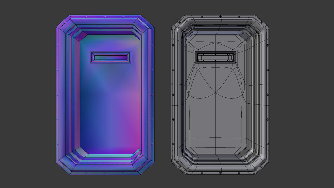
Before baking make sure to have both a LOW and HIGH resolution mesh available, both of which should occupy the same location, be the same size, have the same Origin points and be ‘fixed’ (show side-by-side in the above for clarity – at render they will be co-located and sit atop each other. “Draw all Edges” is also active, found in “Object” Properties, to highlight structural or density differences between the two versions)
In addition the low resolution mesh must be “UV Mapped” with an “Image” assigned, this can be done directly without assignment of any material properties. For this, in the “UV/Image Editor” click “Image” in the Header then “New Image” to access the image properties popup (alternatively click the “+ New” button). Set a “Name” (optional), change the “Width:” and “Height:” as needed based on the shape and size of the mesh, or the expected layout of the UV map (e.g. “1024” by “1024”). Set the ‘style‘ of image to be used selecting one of either “Color Grid“, “UV Grid” or “Blank” from the “Generated Type” selector then click “OK” to confirm and create. The new image will then appear in the UV/Image Editor occupying what was previously the blank “Texture Grid“.
Design note: images created in this way are ‘virtual’, the only significant difference between “Color Grid“, “UV Grid” and “Blank” being whether a pattern or a solid uniform colour is displayed; the latter tends to make it easier to see the UV when unwrapping and editing, whereas the former make it easier to see distribution and relative image density across the mesh – ideally their respective patterns should be reasonably uniform, especially in areas immediately visible to the viewer/player.

Generating a new Image that’s assigned directly to the UV without the use of Materials; the low-resolution mesh is shown in Edit mode to display the UV Map before texture application – the map is slightly distorted due to the default “Texture Space” (grid) being square (high-res shown with “Draw all Edges” active for clarity and highlight structural differences)
If the mesh has not yet been unwrapped select it the 3D View and “Tab” into Edit Mode, press “U” to “Unwrap“, generating an initial map to which the image just created can be assigned. For that, whilst the mesh is still selected, in the UV/Image Editor click the “Browse Image to to link” button and select the image from the ‘browse’ list to assign. Continue to edit the UV as needed so it’s properly mapped to the image. It’s important the low-poly object be properly UV unwrapped before continuing because the map is used to guide the process, it acts as a template into which the interpreted RGB structural data from the high-resolution mesh is rendered.
Design note: the image can be assigned before or after the UV map has been generated and edited, doing one or the other is largely a matter of preference. If done after however, some adjustment to the UV map may be necessary if the image used is not square (the texture grid is square so the UV map will expand when assigned to a wider image). Enabling “Snap to Pixels” helps with editing by making sure mesh vertices align to texture pixels – with the entire mesh selected in Edit Mode to expose the UV’s, click “UV’s” then “Snap to Pixels” in the UV/Image Editor.

Make sure the low-ploy mesh is properly UV unwrapped and has an Image (generated image in the example shown above) assigned before continuing (mesh shown in Edit Mode and selected to display the UV map and image in the UV/Image Editor)
The high-resolution mesh on the other hand needs little additional preparation other than ensuring it’s size/dimension, position and Origin match the low-resolution facsimile – it does not require materials, images or to be UV unwrapped. High-resolution meshes can be used with or without modifiers so it’s not strictly necessary the “Multires” or “Subdivision Surface” modifiers be applied to the mesh beforehand (click “Apply” within each Modifier panel) – the texture baking process is generally capable of understanding such modified structures without issue. Mesh data can also be presented in its original ‘quadratic’ form or optionally tessellated (triangulated), “Ctrl+T“, but this is again not absolutely necessary for the process to work.
Design note: for super-high resolution meshes tessellation may not specifically offer an advantage because they present far more surface volume than pixels are available for a 1:1 correlation. Where it may be prudent to triangulate is in instances where the reference mesh is not suitably dense, which can increase the risk of bake errors where the render process has difficulty determining whether an un-split face is concave or convex, leading to incorrectly baked RGB values.

The high-resolution mesh (selected and shown with “Draw all lines” active) can be ‘sub-divided’ manually (i.e. subdivided through use of the “Subdivide” button in “Tools“) or assigning the “Subdivision Surface” or “Multires” modifier, either ‘fixed’ or ‘unfixed’ (the modifier properties being applied and ‘made real’)
Activating Cycles Render Engine
To access the appropriate tools and properties to bake textures with Cycles the main ‘engine’ used by Blender needs to be changed; whilst it is possible to access some of the same features used by Cycles under Blender Render (the default engine), those specific to it, and necessary for baking, won’t be available. To switch, from the main Header running across the top of the application click the “Engine” drop-down menu, which displays “Blender Render” by default, and select “Cycles Render” from the list. The main 3D View, and a few Properties may change by way of confirmation – materials may appear darker or Scene lighting differ, but little else differs.
Design note: the underlying “Engine” Blender uses determines how Scenes and data are to be displayed and used. Whilst there is a certain degree of cross-over, each also has a set of properties only available per-engine; one notable example relates to the way transparency is displayed – Blender Render shows Materials transparently, Blender Game surfaces, whereas Cycles Render can show both without necessarily needing to switch back and forth.

Change the render “Engine” to “Cycles Render” from the default “Blender Render“. This exposes the needed Cycles properties and options (both meshes are shown side-by side for clarity with the low-poly version in Edit Mode to display the UV Map)
Node Editor
Once Cycles is active Materials can then be edited using the “Node Editor“. Essentially a work space with an infinite grid, ‘nodes’, which are discrete blocks of data, are added to the Scene and linked together to form chains, each block influencing the input or output of a neighbouring node. In this way more sophisticated materials can be created than might otherwise be possible using standard “Blender Render” properties. Baking normal maps however only require a simple material and don’t need any sophisticated set up. To access the “Node Editor“, from the Timeline Header click the “Editor Type” button far-left and select “Node Editor” from the list. The view will change to display the workspace grid. Increase the size of the view by expanding the border between it and the 3D View.
Design note: standard navigation functions operate in the 2D work-space so “MMB” will strafe left/right, up/down, “Ctrl+MMB” will zoom in/out, “RMB” selects/cancels action, “A” select/deselects and so on.

Enlarging the default “Timeline” view – left-click drag the border – and swap it out for the “Node Editor” by clicking the “Editor Type” button in the Header (meshes shown side-by-side for clarity with low-poly in Edit mode to display the UV Map)
Node based Material
Once the Node Editor is accessible, to create a node based Material, with the low-poly mesh selected in the 3D View click the “+ New” button in the “Node Editor” Header, or situated under the Material List (and its three buttons) in “Material” Properties. A new entry appears in the latter and a set of nodes in the former – “Material Output” and “Diffuse BSDF“.
Design note: the two initial values that appear upon creating the new material are analogous to standard materials but allow for greater specificity; “Material Output” options define what the material is – “Surface“, “Volume” or “Displacement” (i.e. polygon, fog volume or structural modification); “Diffuse DBSF” changes the basic characteristics of the material by changing its default “Color“, “Roughness” or “Normal” (i.e. physical colour, material quality or it’s affect on a normal). If the object already contains a standard Material, nodes may not appear (they don’t over-ride properties that already exist which is why the object needs to be blank with respect to material assignments). In such instances, providing Cycles Render is active, an additional button should be visible in “Material” Properties titled “Click to use Nodes“.
Next, to link an image to the new material an “Image Texture” node needs to be added. To do this, from the editor Header click “Add“, “Texture” then “Image Texture” (“Add » Texture » Image Texture“, alternatively “Shift+A » Texture » Image Texture“). A new node block will appear in the scene.
Design note: the “Image Texture” node is analogous to the “Image” subsection of “Texture” properties in a standard material.
Finally to associated the previously generated image with the material, click the “Browse Image to link” drop-down menu button in the “Image Texture” node just added and select the entry shown. This connects the generated image data with the material making it ready for baking.
Design note: the ‘image’ linked to the node can be generated data or a bitmap, either/or doesn’t matter so long as the node contains data.

With the low-poly object selected, click “Material” Properties then the “+ New” button to generate an initial set of options. Two new “Nodes” will also appear in the “Node Editor” – “Material Output” and “Diffuse BSDF” (low-ploy mesh shown in “Object Mode“)

With the nodes in place place a new “Image Texture” node into the scene from the available “Texture” options – “Add » Texture » Image Texture” . A new block appears titled “Image Texture” (low -poly mesh is selected so the material assigned to it can be edited)

From the new node block click the “Browse Image to be linked” drop-down menu button and select the image mapped to the low-poly mesh (mesh objects shown side-by-side for clarity). The node and mesh will update (the latter displaying the image across the mesh if “Texture” view is active)
Texture Bake
Once a Material has been set up, ensure the “Image Texture” node is selected (“RMB“) and click the “Render” properties button. Scroll down to the “Bake” subsection then click the black triangle to the headings left to access its respective properties and options. Here change “Bake Type:” to “Normal” (“Bake Type: Normal“), set “Selected to Active” clicking the checkbox, and adjust “Ray Distance:” to a higher value than “0.000” (i.e. “Ray Distance: 1.000“). Finally in the 3D View make sure to double-check the high-resolution mesh is selected FIRST and the low-resolution mesh LAST – the order is important – then click the button marked “Bake” to generate the map. A progress bar will appear in the “Info” header atop the application, disappearing upon process completion.
Design note: the order in which objects are selected ensures render takes place correctly; the low-resolution mesh, the item assigned the node based material and image, should always be the LAST item (multi) selected (“Shift+RMB“) else the process will error out. Similarly make sure the node holding the actual image reference is active else the process will again error out (“no reference data”). When checking “Bake” settings it’s also useful to have “Clear” set so the process essentially wipes the image and re-bakes the data ‘as new’ when repeating, and “Margin:” set to “16 px” to compensate for UV positions relative to each other where the resulting image is to be used with mipmaps – as mipmaps decrease in size, the distance between UV islands diminishes so a larger initial value is used to compensate for this loss of pixels.

Switch to “Render” Properties and scroll down to the very bottom to access “Bake” options and settings. Change “Bake Type:” to “Normal“, activate “Selected to Active” and change “Ray Distance:” to “1.000” (meshes shown positioned as they should be for rendering, moved together so they occupy the same location on the grid, important for ‘like-for-like’ texture baking)

Make sure the low-resolution mesh is selected LAST (should be active object) then, with the “Image Texture” node selected in the “Node Editor“, click the “Bake” button in “Render” properties to generate the normal map – a progress bar appears in the “Info” header showing progress

The resulting normal map baked to the image previously mapped to the low-res mesh, which can now be saved and used as needed – mapped to an object for game use (note that the entire image, once saved, will need to be re-normalised to ensure it only contains normalised RGB colour values else it may cause issues when used in-game)
Save the Baked Texture
Once bake has finished the resulting normal map appears in the UV/Image Editor where it can then be saved. To do this from the UV/Image Editor Header click “Image » Save as Image” or “Image » Save a Copy“. This opens the “File Browser“. Select a suitable format bottom-left, preferably ‘loss-less’ such as “BMP” or “Targa RAW“, browse to the location the file is to be saved, and then click the “Save as Image” button top-right. Blender will pause and then return to the previous view once done.
Design note: the difference between “Save as Image” and “Save a Copy” has the former save the baked data to a suitable format and then use the new file to over-ride whatever is currently used in the Material, and mapped to the mesh. Whereas the latter will save a ‘copy’ of the same bake data leaving whatever is active in place until the main *.blend file is saved or reloaded – bake data is temporary in nature as such will be lost when doing this (dumped into a temporary data buffer).

From the UV/Image Editor click “Image*” then “Save as Image” or “Save a Copy” to save the data in a usable format (the “*” appended to “Image” indicates generated data has not yet been saved)

In the “File Browser” that opens select a loss-less format to save the image as from the options dialogue lower-left, “BMP” or “Targa RAW” for example, browse to a location to save the file, then click “Save as Image” top-right. Blender will then return to the previous screen once done
Baking & Anti-Aliasing with Cycles
Although Cycles is a more sophisticated rendering engine than Blenders default engine (Blender Render or ‘Internal’), it suffers the same issue with respect to “Anti-Aliasing” in that small details, or areas that including curves or non-perpendicular surfaces or edges, typically appear pixilated, “aliased”, because these types of non-axial surfaces are not interpolated or “anti aliased” – the process doe not yet infer data with respect to clean edges around structural features. The solution, or solutions, to this are the same as they are for Blenders default engine, to generally either; manually edit the resulting image in a photo-editor, or render to an over-sized image and re-size back down so pseudo anti-aliasing happens as a result of the image re-sampling process.
Design note: when editing a Normal map after-the-fact, always make sure to run it through a “renormalize” filter before final export to ensure only valid, normalised, RGB colours are present in the image – non-normalised or other colour disparities can invalidate normal maps causing improper display.
(Additional note: although “Baking textures with Cycles” was written using Blender 2.74, which does not include a direct mechanism to remove or mitigate Anti-Aliasing, future versions of the application are planned to include full AA.)

Textures baked with Cycles suffer the same Anti-Aliasing, or lack thereof, issue as happens using standard (Blender Render) baking. The same solutions can be used to fix the problem however
Broken renders & Cycles
Aside from high-resolution structural detailing being used to determine render quality, the distance between surfaces and the point from which bake calculations are considered is also important – in making a low/high-resolution mesh pair for normal map baking, there is usually some degree of co-planar surfaces, overlap or protrusion between the two – rivets, screws and other features can sit exactly at, above, or below, the low-poly mesh. When the bake process comes across these types of details they may be inadvertently clipped or improperly rendered because the point from which bake is initiated is too close to a surface. The result is typically a broken or incomplete surface or rendering of structure. To compensate for this difference, the distance between surface and render initiation point can be increased or decreased (but not given a ‘negative’ value) using “Ray Distance:” – higher values generally mean more feature capture and render. To adjust the distance, in “Bake” Properties, adjust “Ray Distance:” to a suitable value depending on the significance of detailing that needs to be captured – a “Ray Distance: 1.000” is typically more than enough.
Design note: as a general rule-of-thumb the distance used tends to be reflective of the low-poly structure and the size of features on the high-resolution mesh needing to be captured – the setting to render a flat plain will be tend to be much greater than rendering to a shaped mesh that follows the contours of an object. Distance is also relative to mesh size so larger meshes may require higher values.

With a low “Ray Distance” set normal maps tend to bake with gaps, or incompletely rendered features, due to the close proximity of the ‘ray’ to surfaces of the low-poly mesh – anything that sits above or below a planar surface subsequently may not then render correctly

With “Ray Distance” increased in “Bake” properties, more of the high-resolution mesh detailing is captured and rendered to texture
Mesh Smoothing & Normal Maps
When baking normal maps from meshes, Smoothing tends to be determined by the physical structure of the high-resolution mesh rather than the addition of marked or manually split edges on the low. This is largely because, once high-resolution data has been baked, the ‘sameness’ proximity of individual pixels to their neighbours, and their respective RGB values, determine surface orientation and whether something appears smoothed or not. In other words; meshes are typically smoothed based on the continuity and RGB colour orientation of pixels across a surface rather than surface structure itself, any change in this tends to have a detrimental affect as a result.
Design note: the reason smoothing can be problematic relates to the way normal maps are used to render individual pixels to screen. In essence each pixel represents a single ‘surface’ normal pointing in a particular direction (as indicated by the bluish/pinkish/greenish colour bias of the pixel). When the mesh is actually split (by physically splitting the mesh or virtually using modifiers), the orientation of a normal attributed to a given mesh vertex, and subsequently neighbouring face, define what then becomes a hard edge. This physical data then conflates the RGB values attributed to normals baked to the map represented that section of the mesh; they conflict because they don’t match (normals baked when a mesh section contains a smoothing split differ their RGB bias). This results in the mesh showing a physical edge split (the ‘boundary’ of a smooth ‘group’) whilst at the same time rendering the smoothed surface using normal map data as if it’s not (or rather, it is, but not in the same way). To solve this problem many game engines simply ignore mesh smoothing (in whatever form it takes), assigning instead a single uniform ‘smooth’ value to the mesh (vertices are welded together in instances where they are split) which is then smoothed through the RGB colour data of the normal map.
What this means in practice is that the conditions for baking textures to a low-poly object and using such objects in-game differ; during bake, the low-poly mesh will typically have minimal smoothing in place, if at all, because edges, corners, crevices, bevels and so are defined by the high-resolution mesh and the amount of structure used to describe those types of feature. Whereas in-game, some smoothing may be used to augment the structure with the normal map applied, i.e. splitting an unseen face to aid the appearance of other sections of a mesh.

Low-poly mesh shown with its left side set up to use uniform smoothing, and edges marked as “Sharp” on the right. The baked normal map, shown in the UV/Image Editor, displays the result and what affect smoothing, or not, has on normal maps

Expanded view of the same baked normal map with uniformly smoothed surfaces on the left of each section and edge splits on right; the difference can be quite significant depending on the type of object baked
Summary
The following is a basic summary of the process as a quick check-list for use.
- Make sure both meshes are the same size and at the same location.
- UV map low-poly mesh and assign an Image (without Material).
- High-res mesh can have Subdivision or Multires modifiers active.
- Switch to “Cycles Render” engine.
- Open the “Node Editor” – swap the timeline or other view.
- Add a Material to the low-poly mesh.
- Add an “Image Texture” node to the Material.
- Assign previously created image to “Image Texture” node.
- Set “Bake” options “Normal” and “Active to Selected” in “Render” Properties.
- Click the “Bake” button to generate normal map.
- Save the result to a loss-less format.
Conclusion
Blenders internal render engine (“Blender Internal”) has long been used to bake various types of image map for meshes using the “Texture Bake” system. Despite being a robust tool for this purpose, its an outdated system lacking support for more modern GPU related features and functions that aid and speed the rendering process. As a result its no longer being actively updated (although it is being maintained). Efforts are now instead spent implementing, maintaining and improving the features of “Blender Cycles” render engine as a more viable and modern bundled alternative. Having said this however, until texture baking with Cycles implements anti-aliasing it offers no real advantage over Blenders standard rendering process (largely because without AA Cycles is subject to exactly the same problems, requiring the same solutions).
Video
The video below shows the basic procedure discussed above.

