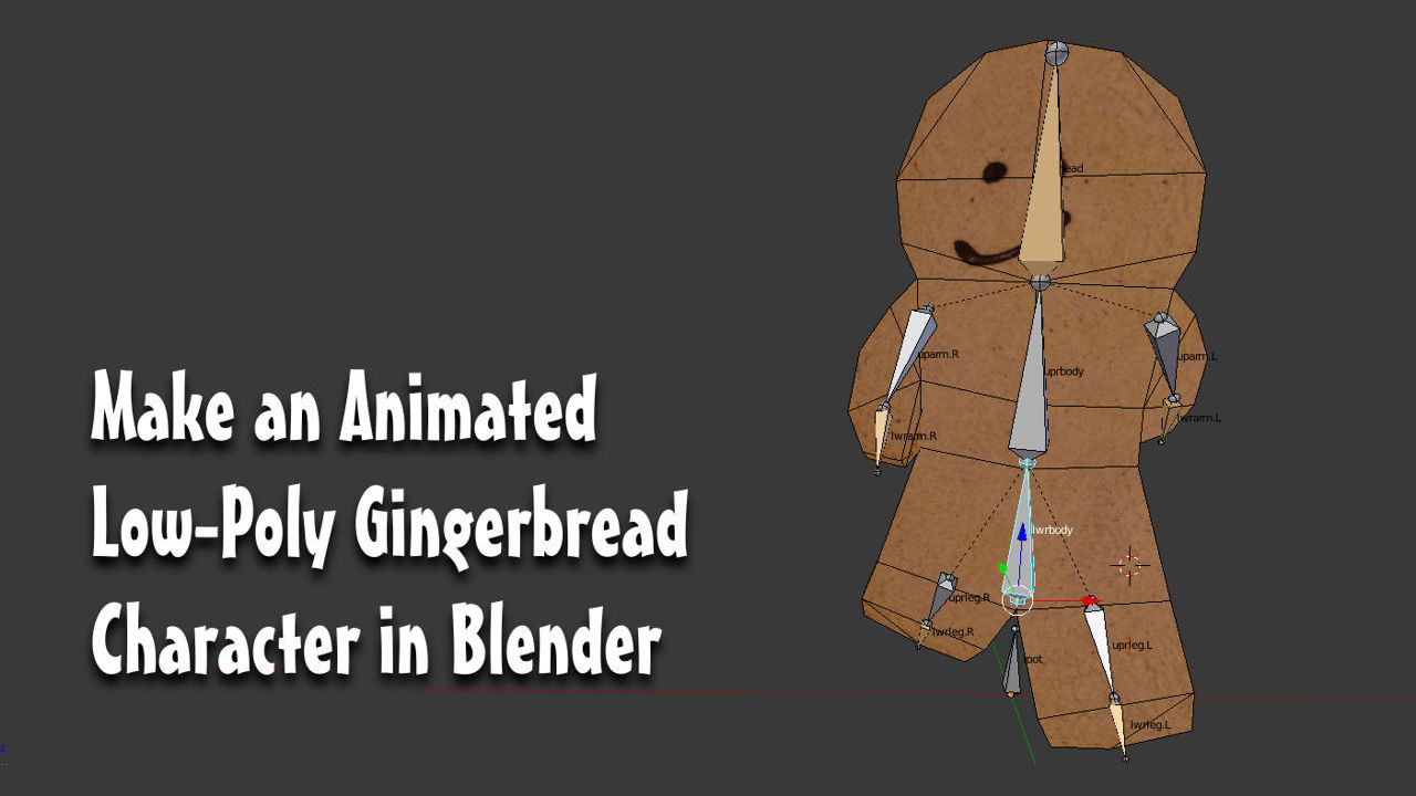
Make An Animated Gingerbread Man – Modelling (#1)
The following tutorial takes the Reader though the process of making a simple animated low-poly Gingerbread character in Blender (any version, Blender 2.50 or above), from the initial start-up file through modelling and modifying the mesh, to Material assignments and UV unwrapping, to rigging and finally animating a simple walk cycle (an animation that loops).
The exercise is suitable for beginners wanting to learn the basic process of making animated characters for games or other similar environments. Although the following exercise is largely for new-comers to Blender, and 3D modelling in general (beginners), it’s not absolutely necessary the Reader be familiar with Blender although it will help if they are.
Download: KatsBits – Gingerbread Character Source (c. 7 MB | *.blend, *.tga). Zip includes each stage of the process as indicated throughout.
Design note: for more on basic Scene navigation in Blender click here, else to recap before continuing; “middle-mouse” (“MMB“) click+hold+drag rotates the Scene; “Shift+MMB” drag strafes left/right and up/down; with “Ctrl+MMB” drag zooming in/out.
– “MMB” = MIDDLE mouse
– “LMB” = LEFT mouse
– “RMB” = RIGHT mouse
– “MMB” = Rotate Scene
– “Shift+MMB” = Strafe Scene
– “Ctrl+MMB” = Zoom Scene
Concepts
The character being made is based on a ‘concept’, an image that will also be used later as the Texture assigned to the mesh (the image the viewer sees when looking at the model). Because of this the image itself is organised as it would be for that purpose, a ‘front’ and ‘back’ representation clearly defined as separate regions of the image so any eventual UV map(s) can be positioned without interference from or with other areas of the image. Normally when using ‘concepts’ as a basis from which to model, they are not usually as well organised because they generally serve an inspirational rather than diagrammatic purpose (a ‘reference‘ rather than ‘blueprint‘ to be copied exactly).
Design note: ‘concepts’ are helpful but not specifically required when working on personal projects. They are however, useful when communicating initial ideas to others so it’s always worth drawing out or collecting together references to get familiar with theidea of using them.

The ‘concept’ image open in a photo/image editor (Corel PhotoPaint in this instance). As can be seen it’s not a ‘concept’ in the normal sense but the texture that will later be assigned to the mesh to provide its surface appearance (of being made from ‘ginger’)
Using a Background Image
First thing to do is to load in a background image (see source file). Press “NumPad 5” to toggle out of “Persp” (“Perspective”) and into “Orthogonal” mode, the Scene ‘flattens’ removing the default three-dimensional perspective, then press “NumPad 1” to switch to what is “Front” view. The Scene will reorient itself to face front.
Design note: background images only display inOrthogonal views – “Front“, “Right“, “Top” etc. so it’s preferential to switch beforehand so as not to mistakenly think the image hasn’t loaded due to theScene still being in perspective mode.
Nextin the 3D View’s Header menu (runs along the bottom of the view), click “View” then”Properties” (“View » Properties“) to open/access the”Properties” panel whichappear to theleft of thewindow.
Design note: as with most functions in Blender there are several ways to open/access or perform an action, in this instance pressing “N” whilst the mouse-cursor is over the 3D View will toggle open/close the “Properties” panel.
Scroll down the panel to the “Background Image” subsection and next to the heading left-click the check box to activate and display the relevant properties and options. Here, click “Open” then in the “File Browser” that appears find the image to be used, left-clicking to select, before then finally left-clicking the “Open Image” button top-right to load.
Design note: when activating options it’s often the case that only the tool section heading and the activate/deactivate checkbox is/remains visible by default. When this happens simply left-click the small black arrow pointing to the right (which flips to point downwards) to open/expose the relevant properties and options. Images need to be square or rectangles unless ‘shaped’ using alpha masks and/or transparency (so long as they are saved to an appropriate format).

From the initial start-up file, open the 3D View’s “Properties” panel and activate “Background Image” down at the very bottom (scroll down) by left-clicking the checkbox

Load an image by clicking the “Open” button in “Background Image” properties, then browse and select the picture with the Gingerbread character on it. Clicking “Open Image” top-right loads it into the 3D View as a background overlay [“background.blend“]
Depending on the size of the image there may be a short delay after which Blender will return to the previous screen displaying the bitmap so its centred in the workspace, i.e. the “Z” and “X” axes of the grid will bisect the image, essentially quartering it, indicating its positioned dead-centre of the 3D View.
Design note: background images do not replace the 3D View’s grid, they augment it (although with that said it is possible to create this effect by turning off the grids display in “Display” setting, again in “Properties). In other words, grid lines and their subdivisions will still be visible throughout. In addition background images don’t affect on “Grid Settings” so they can be adjusted as needed without issue.
Normally this default behaviour can be left as-is but because a particular section of the bitmap needs to be used as a guide for building the Gingerbread character it needs to be moved to one side so the modelling process isn’t made any more complicated than it need be (cf. mirroring). This can be done using “Offset“. In “Background Image” properties again click the arrow to the left side of the “Horizontal Offset” input field (second row from the bottom), this moves the image incrementally to the right offsetting the left side, so the ‘blue’ vertical line (“Z” axis) is positioned approximately centre-mass of the gingerbread man on the left side of the image -the input field value it should finalise at”2.300” or thereabouts, situating the image ready for it to be used as a guide around which the mesh is shaped.
Design note: offsetting the background is not the same as moving the Scene using the middle-mouse button.

The ‘front’ section of the image is to be used to make the mesh so using an “Offset” value position the image so the “Z” axis cuts down the middle – click the ‘left’ arrow of the “Horizontal Offset” input field or “LMB” click to edit and type a value, “2.300” for example
Edit Mode & Blocking out
As with most types of 3D modelling the process of making a character is similarly done in stages, the first typically being to rough out an overall shape, which serves two primary purposes; 1) it guides the rest of the build;2) it creates an initial impression of ‘mass’ or ‘volume’. In other words when starting a project all that’s initially needed is a blocked out form, one that provides a very general impression of the character, its shape, size and dimensions. As this isn’t a sophisticated structure at this point it can be built using extrusions and other basic manipulations of the mesh.
Design note: the full gamut of development typically follows…the initial primitive shape, blocking or roughing out, detailing, materials, UV maps and textures, rigging, animation (and finally export where needed).
First, whilst still in Object mode “Scale” the cube so it’s approximately the width of the Gingerbread characters torso (though not as wide as the arms). To do this press “S” then “X” to resize whilst locked to the “X” axis (side to side) – “LMB” click to confirm. Or from the 3D View’s Header click the “Scale” widget button and “LMB+drag” the ‘red’ handle to expand the mesh, “LMB” release to confirm. This provides the general ‘body mass’ starting point.
Design note: like other functions in Blender the various attributes of “Scale” can be accessed and performed in a number of ways -via shortcut or ‘widget’;
- press “S” to scale on all axes (“XYZ”) equally (‘free’ scale).
- press “S” then either “X”, “Y” or “Z” to scale along a specific axis.
- using the default “Transform” manipulator (the one terminating with arrows), left-click hold on of the pointers, press “S“,then drag to scale in the direction indicated by the arrow.
- activate the “Scale” manipulator in the Header and left-click drag anywhere within the white circle to scale in all directions.
- activate the “Scale” manipulator and left-click hold and drag one of the coloured ‘handle’ to scale along a specific axes.

Use the “Scale” widget (or press “S“) to resize the cube so it’s about the same width as the characters torso (but not as wide as its arms)
Next enter “Edit Mode” by pressing the “Tab” key or selecting “Edit Mode” from the “Mode Selector” in the 3D View’s Header menu (runs along the bottom of the 3D View by default). The Scene will change slightly showing a new set of button and the entire cube will likely be pre-selected, often the default state when starting a project from the start-up file, so press “A” to deselect everything (or from the Header menu click “Select » (De)Select All“).

Switch to “Edit Mode” to begin modifying the mesh pressing the “Tab” key, or by selecting “Edit Mode” from the Header menu and the “Interaction Mode” selector
To make this next step easier to do click the “Face Select” button to the right of the Widget selector used previously (middle of the Header), or press “Ctrl+Tab” to open the “Mesh Select Mode” menu, choosing “Face” from the list. The mesh will change slightly in appearance. Next check to make sure the button to the right of “Face Select” is inactive (off/disabled), the “Limit selection to visible” option – this allows edge selections to be made without interference from surfaces facing the viewer.
Design note: the “Limit selection to visible” button is usually disabled by default but should be double-checked to make sure – when active the buttons background will appear a darker grey colour whilst the icon image itself, the small dots surrounding a surface, will remain relatively light. Note additionally that the “Limit selection to visible” option is only available when the mesh is viewed in “Solid” or other ‘opaque’ display mode -it’s not available in “Wireframe” or “Bounds” due to the ‘transparent’ or ‘wire’ nature of those mesh display modes.
Select the outer right-side ‘edge’ (relative to looking at the screen) by right-clicking (“RMB“) the small black dot that can be seen – this is an ‘origin’ reference point for a given surface. It will highlight as an ‘orange’ line to indicate its selected. Then from the Header click “Mesh » Extrude » Region“, or press the “E“. The selected face will immediately expand outwards following the mouse; move it to approximately the outside edge of the characters arm and “LMB” click to confirm the action. Repeat the process to create the arm on the opposite side, the ‘head’ and ‘lower torso’ areas – click the black dots for each ‘side’, ‘upper’ and ‘lower’ edge, press “E” to “Extrude“, then “LMB” confirm the action (see image below for reference).
Design note: extrusions occur perpendicular to surfaces they’re extruded from, in other words, vertical surfaces result in horizontal extrusion and vice versa. This behaviour is true for all surfaces. If a mistake is made during an extrusion, press “Ctrl+Z” to “Undo” (or from the Header menu select “Mesh » Undo/Redo“).

Using “Extrude” the mesh is blocked out using simple shapes and forms; initially the arms, then head and lower-torso, all approximately positioned to create a roughed-out object
For the legs, although they too are to be extruded a slight modification of the mesh is needed before that can be done; doing so now simply adds another block to the bottom of the mesh instead of two needed, one for each leg. Once the arms, head and lower body have been blocked out, from the Tool Shelf to the left (press “T” if its not visible) click the “Loop Cut & Slide” button (or press “Ctrl+R“) to initiate to the “Loop Cut” tool then, moving the mouse over a horizontal edge of the mesh (side to side), “LMB” click to set the orientation of the intended cut when the pink loop cut-selector appears vertically up the middle of the mesh. The line will change colour, to orange, after which “RMB” click confirm the cut and have it automatically placed up the centre of the mesh (and the selected loop).
Design note: the difference between using “RMB” instead of “LMB” to confirm or carry out an action in this context (loop-cutting) relates to the way the cut is placed – in using “RMB” Blender will confirm selection and the action in a one, automatically placing the cut in the exact middle of the selected surface, whereas using “LMB” the cut can be freely positioned (loop selected) by the user before then being confirmed and cut (the orientation is selected/confirmed and then the cut).

Adding a “Loop Cut” down the centre of the mesh to allow for the extrusion of individual leg sections [“blockout-half.blend“]
Once the cut has been made the legs can be extruded as before – select an ‘edge’ black dot, press “E” to “Extrude” and “LMB” to confirm once the result has been positioned; the legs can also be splayed slightly at this point as this will make further editing easier, so “LMB+drag” the red handle of the “Transform” widget (or press “G“) to the side slightly, in-line with the general position of each leg shown in the background image.
Design note: if the black dots aren’t visible check selection mode is set to “Face“. To do this press “Ctrl+Tab” to access the “Mesh Select Mode” menu and click “Face“. Or alternatively in the 3D View’s Header click the “Face select” button from the “Selection Mode” button array (series of buttons showing a grey cube highlighted to represent ‘vertex’, ‘edge’ or ‘face’ selection options).

The final block-out of the Gingerbread character with arms, legs and head extruded, and with a vertical “Loop Cut” up mesh-centre [“blockout.blend“]
Loop Cuts & Defining Shape
With the mesh blocked out the next step is add a bit more structure so it can be better shaped to follow the general profile background image. This is done by placing a series of additional loop cuts on the left and right side of the body, on the arms, across the torso and across the head. As before then click the “Loop Cut & Slide” button in the Tool Shelf, or press “Ctrl+R” to initialise and then move the mouse over a horizontal edge to one side of the previously cut centre-line, “LMB” click when the pink line appears and then “RMB” to confirm the selection and cut the loop. Repeat for the other side of the mesh, the end result being two additional cuts top-to-bottom, essentially quartering the torso vertically.
Design note: once the orientation of the cut is selected, the use “RMB” in this instance to automatically select and cut the loop is optional because exact precision, i.e. the placement of an exact centre-line through a loop, is not absolutely necessary. Instead using “LMB” to select and then “LMB” again to cut can be used as normal.
To cut horizontally across the body (side to side) move the mouse over a vertical edge then “LMB” click as before to select the new orientation and again to set the cut – in this instance once across the upper torso and arms (the loop should cut around the mesh in a way that includes the arms), and twice for the head. The result should be similar to the image below.
Design note: where multiple loops are needed it is possible to to place more than one at a time; once an edge has been selected to set the orientation, but before confirming for the cut, scroll the middle mouse button up to add (“MMB+up“), or down to remove (“MMB+down“), cuts. To “Cancel” a loop-cut action press “Esc” or “RMB” which will resets the operation, cancelling it as if no cut were made. This differs from “Ctrl+Z” to “Undo” because the latter implies the action has been confirmed and needs to be physically undone, whereas the former doesn’t because a given operation had not yet been completed.

Adding more loop-cuts to the mesh so it can be better shaped to match the background image – as the head needs to be relatively round it contains more loops compared to other sections [“loopcuts.blend“]
Once all the loop-cuts have been made it’s time to shape the mesh. Before doing that however, first a “Display Mode” switch is needed that alters the appearance of the mesh so the background image is visible through it. Whilst still in Edit mode (“Ctrl+Tab“), to the right of the “Interaction Mode” selector (currently displaying “Edit Mode“), click the button with the small white sphere and from the pop-up list select “Wireframe” (or alternatively simply press “Z“). The mesh will change, becoming transparent in appearance. Next click the “Vertex Select” button (to the right of the widget selector) to switch to a mode better suited for this step in the process.
Design note: one of the main reasons for doing this is that “Wireframe” mode allows selections to ‘drill down’ through the mesh – although the object is being viewed face-on (in Orthogonal view), selections propagate down through the mesh so not only the upper element, but all those beneath, can be selected at the same time/through the same action, useful for quick ‘group’ selections or changes.

Switching to “Wireframe” and “Vertex Select” means subsequent selections drill-down through the mesh so not only the element visible to the viewer is selected but also those not directly in view (top and bottom vertices are selected in other words)
Once the Scene has been set up editing can begin. First make a selection. Because both top and bottom of the mesh need to be selected rather than using “RMB” to do this press “B“, or from the Header menu click “Select » Border Select“, to activate the “Border Select” tool. An extended cross-hair appears centred on the mouse cursor. To make a selection “LMB+drag” a ‘box’ around one of the small black dots (vertices). It will change colour by way of confirmation. Then using the “Transform” widget handles, or pressing “G” to ‘free translate’, move the selection so it sits on the outer edge of the Gingerbread character relative to it’s location. Press “A” to deselect and then repeat the process for each vertex around the outer edge of the mesh so each occupies a position such that the result is shaped similar to the background image (see below).
Design note: the ‘feet’ of the character can be shaped using the available structure but an extra loop cut can be made so the area better conforms to the background image – when adding, once the vertical edge is highlighted and the cut direction set (the line turns orange), slide the mouse towards the bottom of the foot before left-clicking to confirm the addition.

Switching to “Wireframe” and using “Vertex Select” makes it easier to see the underlying background image, aiding the repositioning of vertices so they follow the general outline/contours of the character better [“shaped_half.blend“]

The outer edge of the mesh manipulated to follow the general contour of the underlying background image (note the additional loop cut towards the bottom of each leg which allows the mesh to be better shaped to fit) [“shaped_full.blend“]
Once the silhouette is done, press “NumPad 5” to toggle back into “Perspective” view and inspect the mesh, the outline is fine but the mesh is too thick (it needs to be a thin biscuit). This is easily fixed switching back into Orthogonal view and editing the mesh from the “Right” (side view). To do this toggle back into “Orthogonal” mode pressing “NumPad 5” and then “NumPad 3” to switch to “Right” side view. Using “Border Select” again, press “B“, select in turn the ‘front‘ and ‘back‘ of the mesh and using the ‘green’ handle of the manipulator widget, move each side closer to the blue centre-line. “LMB” to confirm after each action. The result should be a much thinner version of the mesh ready for Material assignment and UV unwrapping. Press “Tab” to exit “Edit Mode” (which automatically sets “Object Mode“).
Design note: an alternatively to being in “Wireframe” mode to make selections easier is to use “Limit selection to visible“. If this feature is active whilst in “Solid” display mode (where the mesh is displayed as opaque grey)selections will similarly drill-down through the mesh because ‘back-face culling’, the non-display of elements that cannot be seen, is enabled. “Limit selection to visible” is only available for ‘opaque’ modes of display where the mesh appears ‘solid’.

Inspecting the mesh so far in “Perspective” mode (“NumPad 5“) its noticeably thicker than needed (note mesh is show in “Solid” shaded mode, “Alt+Z“, which also shows, because “Limit selection to visible” was previously disabled/turned off, structure ‘behind’ front facing elements – re-enabling “Limit selection….” would prevent this, displaying only those elements facing the viewer) [“shaped.blend“]

From the “Right” side (“NumPad 3“) and in “Wireframe” (“Z“), it’s possible the entire front surface of the mesh can be selected in a single action (similarly for the back) before being adjust to sit closer to the objects centre – approximately where the ‘blue’ line (representing the “Z” axis) is located

The final mesh ready for the next stage; Material assignment and UV unwrapping [“shaped_thin.blend“]

