Chair – Modelling (#3)
In the first part of Learning Blender 3D we discussed the interface and layout and how the application is essentially composed of a number of key elements.
In part two navigating around a scene using essential keyboard shortcut and mouse controls was discussed.
In this third part both the previous sections will be put to use throughout the process of making a simple kitchen chair model, along the way additional features, actions, control keys and other context sensitive information will be brought into play as we progress and the model takes shape.
The best way to learn how to use Blender 3D is to just get stuck in and make a model or build an object…
So, lets get stuck in.
Download: KatsBits – Chair Source (c. 7 MB | *.blend, *.tga).
Starting a new scene
There’s no need to add any new objects to a scene for this particular project as it will all be made using the cube ‘primitive’ object that’s made available in the default scene.
In case you don’t see the object just create a ‘new’ file by selecting “File >> New” from the Header area menu (as shown below); Blender 3D will prompt you that it’s going to “Erase All” from the scene in order to do this.
Click the ‘warning’ to confirm and a brand new default scene will load – a cube primitive centre stage with a separate light and camera object off to one side (which are not needed but will be loaded as part of a scenes defaults).
The image below shows what should be visible.

Starting a new scene in Blender and loading in the defaults
‘Edit’ mode and editing the mesh object
To make a chair it needs to be shaped by manipulating and editing the mesh itself. To do this we need to be in ‘Edit Mode‘ which gives access to the correct collection of tools and functions to allow the mesh to be cut, shaped and changed to produce the desired general structure of ‘a’ chair.
Zoom into the scene to bring the object closer to view and then Right Mouse Button (RMB) click the object to select the cube primitive – all objects are selected in this way with the Right Mouse Button. Once selected, press the “TAB” key to toggle (enter in/out of) ‘Edit Mode‘, the object will change its appearance to something similar to the image shown below – note the slight change in the ‘tool shelf‘ on the left hand side, a different set of ‘context sensitive buttons‘ have appeared.

RMB selecting the cube primitive and entering Edit Mode [see *.blend “1”]
‘Loop Cuts’ and dividing the mesh
Now we’re now in Edit mode we can go ahead and start to shape the mesh. To do this we’ll need to use an essential tool for any type modelling job called the “Loop Cut” tool – it has a number of different functions in terms of how it edits a mesh, but the basic one is to simply cut a ‘ring’ or ‘loop‘ around a mesh in a particular direction; think of a ‘loop’ as essentially being a cross-section of an object, or think about someone taking a black marker pen and drawing a line around your midriff, that would be a single ‘loop’ which ‘cuts’ around your body following your contours, dips and general shape. A ‘Loop Cut’ on a mesh is essentially the same.
With the object in Edit mode (“TAB“) move the mouse cursor near the mesh and press Ctrl+R to initialise the tool, alternatively press the “Loop Cut and Slide” button in the Tool Self on the left hand side of the screen. A pink line appears wrapping itself around the mesh primitive. This is the loop cut guide. Move the mouse to move the guide and notice that each time the mouse moves over an edge the marker jumps to an orientation that’s perpendicular to that edge. At this point all we’re doing is selecting the direction in which the cut will be made.
Design note: due to a reorganisation of the Tool Shelf, from Blender 2.70 and above the “Loop Cut and Slide” option is located under the “Tools” sub-panel.

Adding loop cuts to a mesh in Blender, use “Ctrl+R” to initialise or click the “Loop Cut and Slide” button in the Tool shelf (under the “Add” sub-section)

From Blender 2.70 the Tool shelf has been reorganised in ‘Tabbed’ sub-pages – “Loop Cut and Slide” is located under the “Tools” panel
Once the direction has been selected, it needs to be ‘set’ so Blender knows it has to lay a loop in the chosen direction. To do this simply Left Mouse Button (LMB) click, the line will turn yellow as confirmation the loop cut will be made in the chosen direction; this then frees the mouse up so it can be used to move the cut guide, setting the exact position of the cut in the chosen direction – at this point the mouse can be used to slide the guide across surfaces, or, on holding down “Ctrl” whilst moving the mouse, the guide will snap to Blender’s grid making it easier to move the mouse with precision over set increments.
Go ahead and slide/snap the cut guide to the centre of the object. For help in doing this look to the bottom left of the 3D View and its menu header, which is temporarily just a gray strip, you should see “Edge Slide Percent:[n]“. As the mouse moves the [n] value will change, when it reads “0.000” LMB click to set the loop cut in place.

Loop Cut will be made along the new ‘set’ guideline
Add two cuts so the object looks similar to the image shown below; both being down the respective centre-line of the “X” and “Y” axis. What these do is ensure that each subsequent cut made on either side of the centreline is evenly spaced and distributed, as we’ll see next when adding some more (the chair is basically made from a series of these cuts).
Design note: as we’re editing a mesh we are now navigating and moving the around Blender in both “screen space” and “3D space“; “screen space” to move the scene (rotate, zoom etc.) and “3D space” to move/manipulate objects along the internal “X”, “Y” and “Z” axis’s.
If you make a mistake at any time, use “Ctrl+Z” to undo the last action or click the “History…” button in the Tool Shelf and select an action to revert to. Remember to use “Shift+” and/or “Ctrl+” MMB to “zoom”, “strafe” and “rotate” the scene as you work.
Design note: for Blender 2.70 and above, the “History…” button is located at the bottom of the “Tools” tab sub-page. Alternatively ‘history’ can be access pressing “Ctrl+Alt+Z” – items listed may vary depending upon current Editor mode.

Two loop cuts placed down the centreline along the “X” and “Y” axis (left-right, front-back) directions on the mesh [see *.blend “1b”]
Adding more loop cuts to the mesh
The next step is add a number of other cuts to the mesh so the various shapes needed for the chair, namely the back and legs can be “extruded“. Using the loop cut process explained above, add four more as shown below. A good tip to use at this point, to ensure all the cuts are same, is to make a mental note of the “Edge Slide Percent:[n]” value as the first of the additional loops is placed. Then, using the value as a reference, subsequent cuts can be made so they all end up being the same distances from previously cut centrelines and the outside edges of the cube – remember to hold down the “Ctrl” key so the loop cut tool snaps to the grid as it moves and the cuts are made. The cube should end up looking like the image below. This is the basic building-block template from which the chair will be made.

Adding extra loop cuts to the mesh in Blender [see *.blend “1c”]
Limit selection to visible (back-face culling)
If at this point you’re seeing something similar to the image below, where the back of the mesh is visible through the front, then it means we need to turn on the “Limit selection to visible” (‘back face culling’) feature so that anything not ordinarily seen gets hidden from view, leaving only visible elements to be drawn. To do this remain in Edit mode and just click the small button that looks like two boxes with dots in the corners as indicated in the shot below.

Turn on Back face Culling to limiting selected to visible [see *.blend “1d”]
Change ‘select mode’
At this point we’re going to switch to a different ‘selection mode‘ from the three types available, “Vertex“, “Edge” and “Face“, we’re currently in “Vertex” but need to be in “Face” select mode. To do this, as shown below, click either the “Face Select Mode” button in the 3D View menu header, or use “Ctrl+TAB” to open the “Mesh Select Mode” pop-up, selecting “Faces” from the list – the way the mesh appears in the scene will change from an object drawn as a series of small black dots (vertexes) joining lines (edges) at corners and junctions, to those same lines with larger black spots at the centre of each delineated surface, these are “Faces” (or more correctly “quadratic polygons” – “poly”, “tris” or “quads” for short).

“Select Mode” in Blender allows us to change between using “Vertex“, “Edge” or “Face” type selection [see *.blend “2”]
Selecting faces and extruding
As briefly mentioned above most object and element selection is done using the Right Mouse Button, we can extend this ability by using the “Shift” key which allow us to de/select additional items. What we’ll do next is use this multi-select feature on a number of faces so we can then use those to make the back of the chair.
Before doing this remember to use MMB to rotate/zoom the scene so you’re looking at, or can clearly see, the top of the mesh (if you’re not already) then hold down “SHIFT” and then RMB click a row of faces along one side of the mesh one face at a time, you should end up with something similar to the image shown below.

Using “Shift+RMB” to select multiple faces in Blender [see *.blend “2b”]
Extrude faces: manipulator widget
Next is to turn these selected faces into the back of the chair using the “Extrude” function. This can be done in one of two ways. Either;
Press “E” to initiate “Extrude“, the faces will jump to show they’ve been extruded, RMB click to released them so they drop back flush the the original faces. Zoom out of the scene (using MMB) to give yourself room, then click-hold-drag the ‘blue arrow‘ of the little ‘gizmo‘ visible near the previously extruded faces. Pull it upwards a distance and then LMB click to set the new position – remember, you can use “Ctrl+drag” to snap the movement to Blenders grid spacing (RMB to cancel and zoom out of the scene further if you find you’ve not got enough room to do this and then try again).

Extruding faces manually using the selection ‘gizmo’ [see *.blend “3b”]

Grabbed faces after click-hold-drag the blue gizmo arrow

Extruded faces pulled up the Z axis to make chair back [see *.blend “3”]
Extrude faces: Tool Shelf extrude region
Or, in the “Tool Shelf” on the left, click the button titled “Extrude Region“, the selected faces will jump to show they’re extruded, RMB click to release the faces and automatically activate the Extrude Region tool options in the lower half of the Tool Shelf (slide the divider to expand the section if necessary). With these options now active the position and orientation of the selected items can be controlled using a series of adjustable ‘distance’ and ‘axis’ parameters (based on ‘unit’ measurement) to move of the initially extruded faces to make the chair back (shown below).
Design note: in Blender 2.70 and above, although tool functionality remains the same, the location of the ‘extrude’ buttons has changed to their being organised under the “Tools” sub-page, accessible clicking the “Tools” tab.

Blender extrude face options in the tool shelf

In Blender 2.70 and above, ‘extrude’ options are located under the “Tools” sub-page
First we need to lock the axis of travel, set a distance value, and then make sure Blender knows what the amends are relative to. To do this type “3.000” in the “Vector” field (“X” and “Y” should read “0.000“). Then in “Constraint Axis” make sure “Z” is checked, then finally that “Orientation” is set to “Normal” from the available options (see image below).

Tool Shelf settings for Extrude Region tools

Extrude options are organised under “Tools” in Blender 2.70 and above, accessible when clicking either the “Extrude Region” or “Extrude Individual” is clicked
What this all does is tell Blender that it should move the selected faces relative to that selection rather than the scene, resulting in the previously extruded polygons now being “3” units above their original position, having been moved up the “Z” axis (shown below).

Chair back done using Extrude Region tools in Blender 2.5 [see *.blend “3”]
Border & Circle Select and selecting faces
The next step is to edit the bottom of the mesh to make the ‘seat’ of the chair. For this we’ll make use of Blenders ‘select’ tools, “Border Select” or “Circle Select“, which provide two alternative ways, in addition to using the RMB, of select the elements we need to modify by using a ‘lasso‘ or ‘paint‘ select process.
To select faces using “Circle Select” press “C“, this will initiate a circular (hence the name) widget tool that can be ‘brushed’ or ‘painted’ over surfaces using LMB+hold+drag to select whatever it touches – note that Circle Select is ‘additive’ so several passes can be made over a mesh with each subsequent selection being added to the previous.
The widget can also be resized whilst in use, providing larger or smaller selection areas using MMB-scroll. If too many faces are selected simply MMB+hold+drag the mouse over them to deselect unwanted elements. Once done selecting the bottom faces of the chair as shown below, RMB to deactivate the tool and return to normal Edit mode.

Circle Selecting faces in Blender

Selected faces after using Circle Select [see *.blend “4”]
Alternatively, to select faces using “Border Select” press “B“. “Border Select” is a ‘box’ selection tool that uses a box or border drawn around elements that need selecting using LMB+hold+drag – note that Border Select is ‘additive’ in that each time an area is draw, any additional elements falling within that boundary are added to previous selections. Selection also automatically deactivates after each pass/use.
To deselect faces after using Border Select, hold “Shift” and RMB click individual faces. Or use Circle Select and MMB ‘paint’ deselect faces.

Selecting faces using Border Select

Faces selected after using Border Select
With the bottom of the mesh selected, rotate and zoom the view so the chair is visible more or less side-on.

Rotate the model so it can be seen more clearly
The red, green, blue widget should be visible (because something is selected). Hold down “Ctrl+Shift” and then LMB click the widgets ‘blue‘ arrow (pointing upwards); using “Ctrl+Shift” snaps movement to the grid using smaller increments allowing greater precision. Move the selected faces upwards about 4/5ths of the original distance between top and bottom of what was the base area (as shown below).
Alternatively the Tools Shelf‘s “Mesh Tools” can be used. The selected faces will need to be moved a short distance so the “Translate” options appear in the shelf (click the blue arrow and move it a short distance), then in the “Z:” axis of the “Vector” section, type “1.600“, the distance of upwards travel.
Using either/or manual or tool based movement should result in the mesh now having an obvious ‘seat’ area similar to that shown below.

Using the ‘blue’ manipulation widget handle, pull the selected polygons at the bottom of the chair whilst holding “Ctrl+Shift” (snap to smaller increments) [see *.blend “6”]
")
Transform options available in the Tool Shelf *after* the initial manipulation has been confirmed (LMB) which then facilitates numerical control over a selection – options change depending upon the manipulation mode; “Transform”, “Rotate”, “Scale”
Extruding individual faces
With the seat area made the next step is to extrude the legs from individual faces. Rotate the mesh so the underside is visible again and press “A” to deselect all the previously selected faces – “A” is a ‘global’ de/select tool that de/selects everything in a scene – then “Shift“+RMB select the four corner faces on the underside of the model as shown below; these will form the basis of the chairs legs.

“Shift+ RMB” click the select individual faces in Blender [see *.blend “6b”]
Rotate the model back round and then extrude the selected faces using the “E” key, hold “Ctrl” to make sure the new faces snap to the grid as they are pulled down to make the legs – note that doing this initiates the “Extrude Region” tools in the Tool Shelf where, as with the back of the chair, the “Translate” options can be used to set the position of the faces by typing or setting the “Z:” axis of the “Vector” section to “-2.000” (that’s negative “2.000”) as shown below.

Extruding chair legs from individually selected faces [see *.blend “7”]

Selections can be manipulated with numerical precision using “Transform” properties which appears after confirming an extrusion using the “E” key to “Extrude” – note in Blender 2.70 and above, the appearance and layout of tools and their properties differ from earlier versions (2.5x as shown above for example)
A third alternative is to click the “Extrude Individual” button after RMB clicking to release the faces, to open up the “Extrude Individual Face” tool options in the Tool Shelf. There are fewer options here but the tool does allow for a similarly controlled positioning of extruded faces (as shown below).

“Extrude Individual” faces tool options[see *.blend “7”]

Options available when using the “Extrude Individual” button in the Tool Shelf (under “Tools“) – options do not appear until an initial extrusion has been confirmed (LMB) or ‘released (“RMB” or “Esc”) after initial step. Note difference between 2.71 (2.70+) bottom, and 2.69- top image – basic tool functionality is the same but their extent, appearance and location may differ between versions
Toggle Object mode
Once the legs have been extruded and positioned that completes the basic structural construction of the chair. Press “Tab” to toggle out of Edit mode and back into Object mode, you should present with something similar to the image below.

Construction of the basic chair done in Edit mode of Blender

Chair in “Object” mode after the initial construction is done to the default cube in Blender [see *.blend “8”]
Additional tools, wire outline display mode
Whilst this tool isn’t specifically necessarily to make the chair, it comes in handy during the modelling process because it places a ‘wire’ around the mesh that acts as a visual aid, helping to distinguish the shape and form of an object because of a thin black outline.
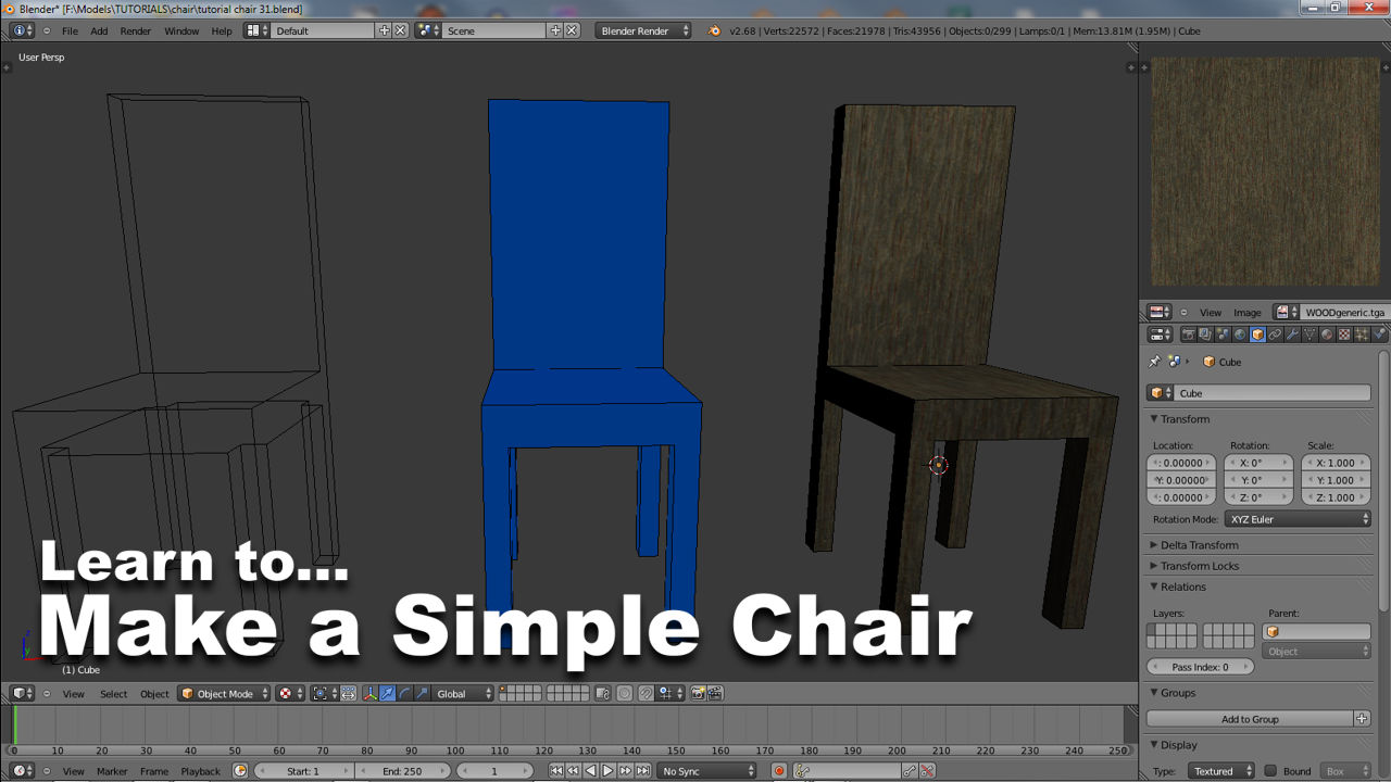
To enable this, select the chair and click the “Object” button of the “Properties” panel on the right. Find “Display” (you may need to scroll down to it depending on your screen resolution) and click “Wire” so the checkbox becomes active (a check/tick will appear) causing the object to display with a thin black ‘wire’ outline (note that this is a distinct feature to that of viewing a mesh in ‘wire-frame’ mode).

Display wire outline in Blender [see *.blend “9”]
Next, the chair needs materials and textures applied to it. Click here to continue onto that part of the tutorial.

