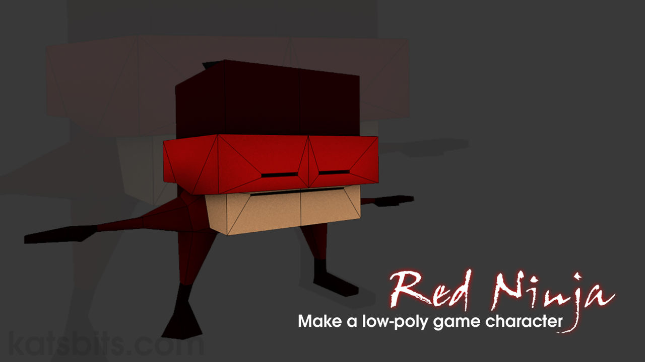
Red Ninja Cubie™ – Meshing & Modelling
Using basic tools and techniques it’s possible to make an individualistic, rigged and animated character even though it may only comprise a few polygons and bones; the challenge in doing so is in the User developing an eye, not for detail, but for expression, the ability of a ‘thing’ to convey an action or emotion that has easily readable meaning.
Download: Red Ninja™ source file (c. 900 KB | *.blend, *.tga).
With this in mind the ensuing tutorial explains the process of making a simple animated character, the Red Ninja cubie™, essentially nothing more than a primitive cube with arm and leg protrusions. With a well placed rig and animation however, it can be highly expressive despite its structural simplicity. A basic understanding of Blender is useful, but not required, to get the most from the following.
Design note: New users to Blender may also find it beneficial to work through the Snowman and/or Gingerbread character tutorials.
Introduction
The general process for making any sort of animated object, be it a simple moving platform or a complex character, can be broken into four core steps; 1) making the mesh, 2) applying textures, 3) rigging or giving the object an underlying skeletal structure; and 4) animation.
Design note: there is an additional fifth step, ‘export’, which, although not covered expressly in this tutorial, has the model built with it in mind.
Each helps inform the process and subsequent steps, so how the model eventually articulates after being rigged depends entirely upon how the mesh was initially built; joints and parts of the mesh that move may need additional structure to prevent collapse for instance, an important consideration for very low-poly objects especially, as is the case with the Red Ninja Cubie™.
Design note: because additional structure can’t be included, the model is essentially designed around it being a ‘cube’, attention will be paid later during animation to prevent.
Before starting, as the character has arms and legs, thought should be given to the initial pose in which the model will stand; a "T", with arms out to the side; a "Y", arms raised above the shoulders, or inverted "Y", hands below waist (cf. illus. 1), as this determines how flexible the mesh is, how well it will deforms when articulated, at the major ‘joints’ in particular, the knees, hips, elbows and shoulders. For the Red Ninja, its low-poly nature, and its overall design, biases towards use of the "T" pose, so that will be used throughout.
Design note: limbed characters are rarely constructed with their arms and legs flat against, too close to, the body, or closed together, because doing so tends to cause mesh deformation problems during articulation, especially when arms and legs are posed at their extremes; arms above the head for example, can result in surface collapse or severe stretching to accommodate a pose, which might then mean altering the mesh and rigging after-the-fact as a fix, an act that might itself cause further problems where implemented as a corrective measure later in the process. Such late-stage changes can generally be avoided or mitigated by considering the type of movement expected of the character beforehand and planning ahead (this is why a degree of forethought and pre-planning is useful before starting).

[illustration: 1] Each of the inverted "Y", "T" or "Y" poses present different challenges with respect to mesh deformation (areas highlighted [1] and [2] above especially) that should be considered prior to starting – for standard bipedal characters the "T" pose is a safe middle-ground option to pose the character during construction

Step 1: Initial Object Setup
As a general rule of thumb character models tend to be symmetrical, both left and right are the same. From a construction point of view knowing this, that characters are often in effect mirrored, means it’s possible to significantly reduce the amount of work necessary by actually doing this, mirroring the mesh. What this essentially means is the one side acts as a ‘master’, the other a ‘duplicate’, when the former is changed or modified, the latter automatically updates. The mechanism to do this varies depending on the complexity required in terms of the build process, but at its essence using a simple ‘linked duplicate‘ is all that’s needed. This will be the first step to be done in preparation of mesh editing.
Design note: it’s generally preferable to set this up before doing any significant modification to the mesh to eliminate alignment issues early on – if not corrected at this point misalignments can go on to cause larger issue later on in the process (subject to the characters complexity).
To begin, right-click select the default Scene Cube and press "Tab" to enter Edit Mode. As mirroring is a duplication only half the object is needed so, left-click the "Loop Cut & Slide" button in the Tool Shelf and mouse back over the mesh.
Design note: "Loop Cut & Slide" is found within the "Tools" tab, "Add" sub-section. Alternatively press "Ctrl+R"; activating loop cut automatically places Blender into "Edge" select mode, normally available using "Ctrl+Tab" or the "Mode Selector" in the 3D Views header.
The pink loop cut guide appears. Position the cursor over the leading edge of the mesh (upper or lower edge of the front face) and left-click to select and set the cuts orientation. When the orange line appears right-click to have Blender automatically place the loop centred on the mesh (cf. illus. 2).
Design note: when placing a loop cut Blender provides two options as to how that is done once the orientation has been set/selected; 1) the cut can be set based on User input when left-click is used – indicator slides back and forth, or 2) automatically centred when using right-click – centre-line is determined based on surface information and cut automatically placed.
Next, using "Shift+" right-click ("Shift+RMB"), select the right side of the mesh (toggle "Face" select mode "Ctrl+Tab" to make this easier to do) and either delete the selection outright, "Del", or detach it using "Separate", "P".
Design note: keeping the detached elements is not specifically required and can be kept for reference, especially so if mesh mirroring is done later – the character is built up a degree before being mirrored. As an alternative to using "Shift+RMB" to multi-select, "Border Select", "B", or "Circle Select", "C", can also be used but will typically necessitate the mesh being in "Wireframe" view (press "Z"), or that "Limit selection to visible" be disabled in the 3D Views header – it’s often easier and quicker to "Shift+" multi-select, taking advantage of the Scene defaults rather than switching between various modes of operation.
Press "Tab" exiting Edit Mode and with the remains of the object still selected, in the 3D Views "Object" menu left-click "Duplicate Linked" ("Object » Duplicate linked" or alternatively use "Alt+D"). A new instance appears moving with the mouse. Right-click to release and reset the new object to its default position on the same side and coincidental with the original.
Design note: for linked duplicate to work meshes should be in Object Mode because the procedure is replicating the entire item and associated properties, not just the mesh data/structure.
This new item needs to be flipped to the opposite side so whilst its still selected, from the "Object" menu again select "Mirror" then "Y Global" ("Object » Mirror » Y Global", alternatively "Ctrl+M » Y"). The object will flip across the selected axis, "Y" in this instance, mirroring the original. Left-click or press "Enter" to confirm and set in place. With this done modifying either Object instantly mirrors across to its partner (cf. illus. 3).
Design note: linked duplicated objects are just that, linked; either object of the pair can be edited with those changes duplicating across to the other (non-selected object) without user input.

[illustration: 2] Divide the mesh in half clicking the "Loop Cut and Slide" button (shortcut "Ctrl+R") – mouse-over a horizontal edge, left-click to select then right-click to auto-place a centred cut around the mesh (forming a centre-line) [000_cubie.blend]
 original")
[illustration: 3] Select and delete one half of the mesh (or separate, "P", and put to one side) then back in Object Mode, make a "Linked Duplicate" (shortcut "Shift+D") and "Mirror" the copy across the front/back "Y" axis ("Ctrl+M » Y"). Changes made to one half will then automatically duplicate to the other (only one half need be edited) [00_cubie.blend]
Step 2: Blocking Out
With the base unit duplicated and mirrored editing can begin. With the original half (still) selected (right-click if not), "Tab" back into Edit Mode and left-click the "Loop Cut & Slide" button again to add another cut, this time positioning the mouse over a vertical edge so the cut loops around the horizontal. Left-click to select the orientation then right-click to confirm and auto-centre the cut, essentially dividing the mesh in two, creating an upper and lower section. Once done, the basic structure needed to define the character can be blocked out, namely the arms and legs.
Design note: the number of loop cuts initially made should be kept to a minimum to maintain the characters overall simplicity; additional cuts can be made when needed or determined by the build process.
The first section to define is the shoulder and hip, an intermediary ‘buffer’ between limbs and torso that accommodates better articulation of the former without unduly deforming the latter, important in limiting mesh collapse when the character is moving.
Design note: without the additional structure the mesh might collapse at the shoulder and /or hip when the arms and legs are articulated; the ‘buffer’ alleviates this by localising deformation to the region.
To do this switch selection mode to “Face select“, “Ctrl+Tab » Face” (alternatively from the 3D Views header left-click the mode selector button displaying the face icon), then using “Shift+RMB” multi-select the underneath and lower-side faces of the mesh, essentially an "L" shaped selection that wraps around the lower side corner, before then left-clicking the "Inset Faces" button in the Tool Shelf (alternatively press "I"). A new set of inset faces appear. Move the mouse to reduce or increase their size until this new region is approximately one-third the depth front-to-back of the mesh. Left-click to confirm and set in place (cf. illus. 4).
Design note: "Inset Faces", similar to other ‘generative’ functions, adds material that’s ‘active’, it moves with the mouse as a active selection. As such it can be positioned with immediate effect using left-click, or reset to its original position with right-click. Should an accidental placement occur the action can be undone using "Ctrl+Z" (removes or resets the action and any elements created).
With the new faces still selected left-click the "Extrude Region" button in the "Tools" tab of the Tool Shelf (alternatively press "E"). Another set of faces appear this time traveling along an axis perpendicular to the selection when the mouse is moved; position the cursor a short distance away from the main mesh and left-click to set, creating a shallow stepped protrusion, the shoulder/hip section from which the arms and legs will emerge (cf. illus. 5).
Design note: when extruding the default behaviour, aside from moving with the mouse, is for the new element(s) to travel along an axis whose direction is averaged from the original selection, i.e. two faces at right-angles to each other will produce a new selection at 45°, the mid-point between 0° and 90°. As a result this behaviour can produce extrusions at odd, irregular, angles.
To create the basic arm and leg blocks, right-click each individual outer facing surface of the protrusion in turn – the outer side, and outer underside faces, not the surrounding border – and once more left-click the "Extrude Region" button in the Tool Shelf (or press "E"). Another new structure emerges perpendicular to the original selection; for the arm move the mouse a short distance to the side away from the body, left-click to confirm; for the leg move the mouse below the body, left-click to confirm. This creates two basic, blocky arm and leg sections (cf. illus. 6) completing the initial but basic ‘block-out’. Next the mesh needs to be shaped and detailed.
Design note: when extruding individual faces it generally doesn’t matter which ‘extrude’ button is selected – "Extrude Region" or "Extrude Individual" – because they both produce the same result; an individually extruded face.

[illustration: 4] Right-click select the bottom and lower side faces then inset using "Inset Faces" in the Tool Shelf (shortcut "I") to create a new set of faces from which the limbs will be extruded [02_cubie.blend]

[illustration: 5] Whilst the new faces are still selected, click "Extrude Region" to create a small protrusion – when extruding, new material typically extrudes along path based on an averaged angle between members of a selection, in this instance at 45° angle to the 90° formed by the faces initial selected (45° being the mid-point of 90°) [1_cubie.blend]

[illustration: 6] Select each face of the protrusion in-turn and extrude as individual elements to generate a basic ‘arm’ and ‘leg’ section, which formulates a basic ‘block-out’ of the character – all the essential elements are present and roughly positioned and proportioned [2_cubie_blockout]
Step 3: Shaping (first pass)
Once the block-out stage is completed the mesh is ready for a first pass at shaping. This is done ostensibly by manually sub-dividing selected elements to facilitate their being scaled, shaped, manipulated into positions that better represent what they are, i.e. arms, legs, or within that, wrists, ankles etc. The primary tools for doing this are "Loop Select" and "Scale".
Design note: before continuing with the build a moment should be taken to assess the relative length or the characters arms and legs; it’s preferable to establish their length before doing too much work to avoid adjustments later on that might be complicated due to the presence of other structures or features – whilst this might not specifically be a problem for a low-poly character like the Red Ninja, it can be for more complex shapes where more structural data needs to be adjusted.
[illustration: 7] Length of the limbs, arm and leg, relative to the torso, in this instance a little over three-quarters the width/length of the main torso
")
Before adjusting the mesh however, the limbs need to be selectively subdivided so each can be better shaped for purpose. This is done using the loop cut tool to place multiple cuts around the mesh.
Design note: in this context ‘subdividing’ is used in its traditional sense of something being dividing into two, no subdivision tools or modifiers are used.
Whilst still in Edit Mode ("Tab" if not), left-click the "Loop Cut and Slide" button in the Tool Shelf (or press "Ctrl+R") then when the mouse is moved back over the mesh, scroll the middle-mouse button up or down to increase or decrease the number of cuts to be made – as indicated by the number of pink guidelines – for example, mouse over an horizontal edge belonging to the arm and scroll up until three (3) pink guidelines appear, left-click to set the orientation, then left-click again to confirm. Repeat the process for the leg, scrolling up until two (2) pink guidelines appear (cf. illus. 8).
Important: select mode automatically switches to "Edge select" when using "Loop Cut & Slide" regardless of current mode ("Face" or "Vertex"), "Ctrl+Tab » [mode]" may therefore be necessary to re-engage the previous mode.
Design note: once the orientation of the loop cuts has been selected with the first left-click, using right-click will automatically distribute the cuts along the element being sub-divided, left-click confirms manual placement. Using either one doesn’t matter in this instance.
With these new cuts in place the arm essentially comprises (outwards from the torso); an upper (first sub-division humorous), lower (second sub-division ulna/radius) and hand (third and fourth sub-divisions *carpal’s). For the leg (outwards from the torso); upper (first sub-division femur), lower (second sub-division tibia/fibula) and foot (last sub-division *tarsal’s).
Design note: each section is generically representative of its flesh and bone counterpart to ensure relatively accurate articulation despite the low structural detail of the mesh.
To make each look more limb-like switch selection mode to "Face" ("Ctrl+Tab » Face") and change the "Transform manipulators" mode to "Scale" (left-click "Scale" in the 3D View Header [cf. illus. 9], or press "S") before then pressing the "Alt" key whilst right-clicking the second loop of faces around the arm to select. The manipulator widget will be centred on the group. Next left-click drag in turn the green (front to back) and blue (top to bottom) end markers (small cubes) towards the arm section reducing the selections size to about 1/4 their original height/width, creating the impression of the lower or forearm. Release the left mouse button to confirm (or left-click to confirm when using free-scaling, "S").
Design note: selections can be scaled using the widget or by pressing "S" to initiate ‘free-scale‘, the difference is largely one of personal preference, and to a lesser degree, control. Using the widget for example, immediate access to individual axes is available, whereas additional keys need to be pressed in free-scale mode, "X", "Y" and "Z". On the other hand, free-scaling provides immediate access to uniform scaling, whereas the inner-circle of the widget (which initiates uniform scaling) can be overly sensitive to cursor movement by comparison. The choice also affects how each operation is confirmed, because left-click initiates the widget, actions are confirmed and set by simply releasing the mouse button. In contrast because free-scaling is initiated pressing "S", actions have to be confirmed with a left-click (alternatively in both instances an action can be confirmed pressing "Enter", or cancelled with a right-click – note that for widget use, right-click only work during an operation, not after it, i.e. right-click has to be used whilst left-click is actively doing something).
To shape the basics of the hand, right-click the very outer face at the end of the arm section, press "S" and down-scale it to approximately 1/4 its original height/width (pinches down in size). Left-click to set (when using "S" to scale, or left-mouse release when using the widget and/or widget handles).
Design note: scaling is approximate as it can be adjusted later if necessary.
For the leg, similar to the arm, "Alt+right-click" loop-select the second row of faces (middle row of the section), press "S" to free-scale or use the green (front to back) and red (left to right) handles of the "Scale" manipulator to narrow the section creating the impression of a lower-leg or shin. Left-click or left-click release to confirm (depending upon how the scaling was done). Leave everything else as is for now as this first pass essentially establishes the basic appearance of the structure ready for subsequent tweaks and modification (cf. illus 9).

[illustration: 8] Using "Loop Cut and Slide" place 3 loop cuts along the arm and 2 up the leg (middle-mouse scroll up to add, right-click to auto-place) [2_cubie_loopcuts.blend]

[illustration: 9] Shaping the mesh making loop based selections – press "Alt" whilst right-clicking a face ("Alt+RMB"), switch to the "Scale" widget (shortcut "S") and scale selections inwards to shrink, shaping lower limbs segments [4_cubie.blend]
Step 4: Shaping (second pass)
The second pass at modifying the mesh finalises the figurative appearance of the characters limbs in terms of their overall shape, size and orientation; specific adjustments are to be made so the limbs make sense physically and mechanically. As before much of the process is done using "Scale", either uniformly or across a specific axis, and frequent selection mode and type switches (between face, edge or vertex elements, and single, multi or loop selections) depending on how finite a change is required.
Design note: generally speaking once the basic shape of something is made, most of the effort expended during the modelling process is in editing and modifying the mesh into a finalised state. This often entails a lot of fine tuning and adjustment of individual elements, which is why blocking out basic forms is important – doing so affords the creator an ability to focus simply on shaping the final form without being too concerned that the underlying structure might need to be changed as work is done.
To make each arm and leg convincing relative to being stuck to the side of a cube their respective shapes need to be modified so they taper towards the end, terminated by a block representing hand and foot, with elbow, knee, wrist and ankle joints formed from specifically positioned edge loops (that will eventually articulate).
Design note: when thinking about the size and shape of limbs, relative proportion is key, not just in how that relates to a specific limb, but also how said part fits together with other elements of the overall character; one of the reasons for using a block out and first pass is to rough out the general proportions of the character quickly and cheaply – though a design may be predetermined and set on paper/screen, literal interpretations don’t always work, so some adjustment is typical, which early shaping stages allow for.
First address the width/taper of the arm. Toggle into "Edge" select mode ("Ctrl+Tab » Edge" or click the ‘Edge’ icon in the 3D View header) and using "Alt+RMB" select the second loop of edges (cf. illus. 10, "2a"). Press "S" and uniformly re-scale the group larger by approximately 50% their previous height/width. Left-click to confirm. This begins to form a slight taper to the limb. Next "Alt+RMB" select the fourth loop (cf. illus. 10, "4a") and left-click drag the blue handle of the "Scale" widget (select from "Transformation manipulators" in the 3D Views Header if not set) and re-size the selection to the same height as loop "3a" – this loop is part of the hand, and should be about the same height as the wrist/lower arm. Then to complete, move loop "4a" closer to loop "3a" using "Translate" – press "G" to initiate then "X" to lock the axis. Left-click to confirm. The result should be a simple wedge shaped hand, narrows at the wrist, gradually widening towards the shoulder (cf. illus.10-13).
Design note: as with "Scale", "Translate" can be initiated using a shortcut, "G", or switching "Transformation manipulations" mode using the selectors in the 3D View Header. Either/or performs much the same way as "Scale" in that using the shortcut puts the operator into ‘free-translate‘ mode so another key would then be needed to lock movement to a specific axis ("X", "Y" and "Z"), whereas simply left-click dragging a widget handle performs the same action. Similarly, free-translate actions are confirmed with a left-click, widget handle operations, a mouse button release (from being pressed/held down).
The leg is similarly treated in that it too should taper from hip to the ankle. Using "Alt+RMB" select the second loop of edges (cf. illus. 10, "2b") down from the hip – this will be the knee – press "S" and uniformly scale up by approximately 50% the previous height/width. Left-click to confirm. To change the location of the loop press "G" then "Z" to lock the axis, then move down a short distance (cf. illus 10, "2b"). Left-click to confirm. Repeat for the ‘ankle’ loop ("3b"), lowering that to decrease the relative height of the foot – which should also be narrower at the back (heal) so right-click that individual edge and left-click drag the red widget handle (should still be in "Scale" mode) creating a wedge shape of the foot block.
Design note: using "G" in this context negates the need to switch the widget back and fourth between "Scale" and "Translate", this way "Scale" can remain the selected widget type under "Transformation manipulations" whilst being over-ridden in a ‘local’ sense when "Translate" is initiated using the shortcut.
Once the immediate changes have been made, to better position and scale them relative to each other and the limbs they represent, toggle between perspective and orthogonal view to adjust and align the leg so it splays slightly outwards in "Front" view ("NumPad 1"), and has a slight forward kink at the knee when viewed from the "Left" ("Ctrl+NumPad 3") – "Alt+RMB" select edge loop "2b" then use "Shift+Alt+RMB" to add "3b" and "end" (foot) to the group, using the "Translate" widget left-click drag the red handle outwards causing the leg to angle slightly; the foot should be placed under the armpit. Release to confirm (cf. illus. 10 & 12).
Design note: alternatively when manipulating the leg section, left-click the "View" menu option in the 3D View Header and select the orientation from the list; "Front" ("NumPad 1"), "Left" ("Ctrl+NumPad 3"), "Right" ("NumPad 3") and "Top" ("NumPad 7"), toggling between "Persp/Ortho" also help ("NumPad 5").
Once the leg is repositioned the foot can then be rotated using the "Top" view – "Alt+RMB" select "3b" then add "end" (foot) using "Shift+Alt+RMB", press "R" and rotate the group about "5°" clockwise (looking down). Left-click to confirm. Finishing up this stage, the arm can then be adjusted to have a backward kink at the elbow (when viewed from the top) with the hand slightly forward of the shoulder – using "Alt+RMB" select edge loop "3a" then include "4a" and "end" (hand – see below) using "Shift+Alt+RMB", press "R" and rotate "5°" counterclockwise. Left-click to confirm. Finally press "G" and reposition the selection slightly forward of its original position causing a bend in the arm at the elbow. Left-click confirm completing the second pass at defining the mesh (cf. illus. 10-13).
Design note: "Rotate" doesn’t need to be used exclusively to twist the foot as its useful for making slight adjustments to other elements and selections. Press "R" to initiate then "X", "Y" or "Z" to lock the axis, or alternatively left-click the "Rotate" selector in the 3D View header (which remains active, but can be over-ridden if a different transform, scale or translate, is used).


[illustration: 10-13] Using ‘Scale’ ("S") alongside ‘Translate’ ("G"), the initial pass at shaping the arm, leg and shoulder is done – each section is scaled and positioned relative to the overall appearance of the character. Limbs also include slight kink at elbow and knee creating a more natural ‘resting’ position ("T" pose) allowing for better articulation once rigged and animated [5_cubie.blend]
Step 5: Origin
With the second pass complete and the mesh starting to look more figurative, its position relative to the Object Origin, the small sphere that’s visible when the object is selected, should be checked and (re)set where necessary so the mesh is located correctly in relation to it, i.e. Origin at grid centre ("0,0,0" where the cardinal axes cross) with mesh standing over it, also centred. Although addressing this issue can be done at any point it’s generally preferable this be done early to avoid problems later, especially as might occur during rigging.
Design note: the Origin is the small sphere that’s visible when an Object is selected (most ‘types’ of Object have one, Mesh, Armature, Empty etc.). Its a fixed point in 3D space around which objects are formed and measured locally (e.g. helps define the objects dimensions) and globally (defines an object position in space relative to the Scene). It defaults to centre-of-mass so mesh editing tends to mean having to relocate either/or Object or Origin at some point, an issue fixed in Edit or Object mode depending on which (mode) is active, and where the Origin is in relation to where is needs to be.
Whilst still in Edit Mode ("Tab") switch to "Front" orthographic view, "NumPad 1" (press "NumPad 5" first if not already in Ortho view from previous), then from the "Select" menu in the 3D View Header click "(De)select All" to select the entire mesh (alternatively press "A").
Design note: pressing "A" will select or deselect all objects ("Select » (De)select All") depending upon there being something already selected or not. If not "A" will select all. If there is "A" will deselect all (clear) that selection. This usually leads to "A" having to be pressed twice, once to clear current selections, then again to select all – normally simple mouse selections clear previous selections unless "Shift" is engaged as part of a broader group selection.
Once the entire mesh is selected, using the "Transform" widget, left-click drag the blue handle upwards until the underside of the characters feet are level the the horizontal axis (red line). Release to confirm. Alternatively press "G" then "Z" to lock the axis and move the mouse upwards taking the mesh with it until the bottom of the feet are parallel with the horizontal plain. Left-click to confirm (cf. illus. 14).
Design note: if the Origin isn’t reset and the character exported for use, it will appear ‘zeroed’ on the Origins location and buried in the ground plain up to that point, e.g. buried up to the waist.
Alternatively, to reset the Origin in Object Mode. Exit Edit Mode, "Tab", and right-click select the mesh object (now back in Object Mode). Make sure the "Translate" transform widget is active (select the "Translate" widget operator in the 3D View Header) then left-click drag the blue handle upwards until the underside of the characters feet stand on the horizontal. Release to confirm (alternatively press "G" then "Z", reposition as above, left-click to confirm). In "View" Properties ("N") ensure the "3D Cursor" properties are set to "X: 0.00000", "Y: 0.00000", "Z: 0.00000". Then in the Tool Shelf under "Tools" left-click "Set Origin" and select "Origin to 3D Cursor". The Origin resets to the cursors location.
Design note: when using either approach ensure the mesh ends up centred over the Origin in "Front" ("NumPad 1") and "Right" ("NumPad 3") side views.

[illustration: 14] Once the basic proportions are defined the mesh is repositioned so it sits correctly relative to the Object Origin being at the characters feet – this can be done at any point but is typically set once the initial (build) pass is made to avoid later complications [5a_cubie.blend]
Step 6: Detailing – Hand & Foot
Once the general proportions or the arm and leg have been finalised (cf. illus. 15), using "Edge select" and "Subdivide" the ‘foot’ and ‘hand’ can be modified and better shaped to represent what they are supposed to be.
Design note: again the purpose is to gradually refine shapes rather than attempt to finalise this early, that way adjustments can still be made with relative ease without upsetting too much structure. In other words, only the basic shapes of the hand and foot are formed, further adjustments can be made later.
Switch select mode to "Edge" ("Ctrl+Tab » Edge" or left-click the "Edge select" button in the 3D View Header) then reposition the scene to focus on the hand.
Design note: a quick way to fully focus on something is to right-click select an element of it (or something nearby) and press "NumPad ." ("NumPad Del"), or from the "View" menu in the 3D View Header select "View Selected" ("View » View Selected"). The viewport camera will instantly focus on, and subsequently spin around (MMB), the new selection.
To adjust the hand "Shift+RMB" multi-select the two front leading edges of the hand (cf. illus. 15) and in the "Tools" tab of the Tool Shelf left-click the "Subdivide" button. A new edge immediately appears perpendicular to, and centred on, the previously selected edges. Right-click select the new edge (clearing the previous selection) and using the "Transform" widget handles (or press "G"), left-click drag the green ("Y") and red ("X") pointers in-turn moving the new edge in and back slightly to create an indentation, a thumb.
Design note: in this context "subdivide" is not the same as "subdivision" – one describes a tool or operation function, the other a broader outcome. In practice this means splitting or dividing a specific element selection (and ‘edge’ here is an element defined by two vertices that can be selected either as an edge element, or as the consequence of selecting two vertices). Vertexes cannot be split/divided using this tool, only the edges/faces/surfaces between them.
Similarly for the foot, right-click the leading edge at the front and again left-click the "Subdivide" button. This time instead of an extra edge being created the action simply divides the selection, placing an additional vertex mid-point along the edge representing the division. To shape the foot/toes switch select mode to "Vertex" (click the "Vertex" transform button in the 3D View header, or press "Ctrl+Tab » Vertex"), if the new vertex is not pre-highlighted right-click to select then using the "Transform" widget (or press "G" then "Y") left-click drag the green handle, moving it forward slightly of it’s current position. Release to confirm. Right-click the vertex outside corner, front edge and move it back slightly. Together the two changes form a shallow point forming a rough approximation of toes (cf. illus. 16).
Design note: when dividing a single edge selection the resulting division is of the selection itself, i.e. it will divide the edge in two, placing an additional vertex (not visible unless "Vertex" select mode is active, else the junction/division will be represented by a ‘joint’ between the two dividing edges). Typically this type of isolated division forms an ‘n-gon’, a face that has more than four sides/corners.


[illustration: 15 & 16] First pass detailing the hand using "Subdivide" to split the upper and lower leading edge creating a simplified ‘thumb’, and similarly to the foot creating basic ‘toes’ – switch "Selection Mode" between "Edge" and "Vertex" to position the latter more easily [6a_cubie.blend & 6b_cubie.blend]
Step 7: Detailing – Initial Head & Face
For the Red Ninja’s face extra structure needs to be generated before shaping. This is done using Subdivide again, along with two new operations that restructure surfaces to facilitate better editing, "Triangulate" and "Join". First "Shift+RMB"multi-select the vertical edges of the lower front and back face of the torso section (cf. illus. 17 – green lines) and left-click the "Subdivide" button in the Tool Shelf. Two new horizontal edges appear, one per face, cutting front and back face in half and forming a centre-line approximately shoulder height (cf. illus. 17 – red line) – the cuts don’t propagate around to neighbouring faces on the side of the torso, instead the division creates an "nGon", a multi-sided polygon, that needs to be optimised before use (cf. illus. 17).
Design note: an "nGon" is a face that has more than four edges, which typically requires their being restructured before being edited – left ‘as is’ n-gon’s behave like ‘terminal junctions’ because cuts don’t propagate across/through them.
To do this switch to "Face select" (if not already active), "Ctrl+Tab » Face", and right-click the nGon. From the "Mesh" menu in the 3D View Header, select "Faces » Triangulate Faces" (alternatively press "Ctrl+T"). The nGon will immediately break into a series of individual triangles, three in this instance (cf. illus. 18 – green, yellow & orange areas). To reorganise the triangles revealed, "Shift+RMB" select the lower pair (cf. illus. 18 – yellow & orange areas) then from the "Mesh" menu again, click "Faces » Tris to Quads" (or alternatively press "Alt+J"). This immediately merges ("Join") the separate triangles together forming a single four edged face (cf. illus. 19 – orange area). Repeat the process for the face behind the shoulder created as a result of dividing the rear face – this too will be an nGon in need of similar treatment so right-click to select, "Ctrl+T" to triangulate then "Shift+RMB" the lower two and use "Alt+J" to create the necessary quad. Once both front and back faces have been structurally reorganised the characters head and face can be constructed.
Design note: "Triangulate" ("Alt+T") and "Join" ("Alt+J") can be used in a general sense as a tool to more broadly reorganise structure for better editing.
")
[illustration: 17] Second pass detailing includes the initial cuts needed for the bandanna – select front and back vertical edges (green) and use "Subdivide" to split (blue) producing an nGon (pink) – a surface with more than 4 edges (red) [7a_cubie.blend]

[illustration: 18] In dividing the front and back face an "nGon" is created that needs to be restructured using "Triangulate" (shortcut "Ctrl+T") – select the lower two faces (2 & 3) and "Join" back together to form a ‘quad(ratic)’ face (shortcut "Alt+J") [7b_cubie.blend]

[illustration: 19] The reorganised new faces, front and rare, better defines the torso/body central region, which can now be used to create the bandanna [7c_cubie.blend]
Step 8: Detailing – Bandanna
With the new edges in place and faces reorganised the Red Ninja’s torso is essentially split into three sections, a top, an upper and a lower. The bandanna, the next significant structure to be added, and face, will be made using the upper and lower areas. First the bandanna. Switch to "Face select", "Ctrl+Tab » Face" (left-click "Face select" in the 3D View Header), then using "Shift+RMB" multi-select the upper loop of faces that wrap around the cube (physically the middle of the mesh), that is the front, rear and side panel (including the two triangles). This loop forms the basis of the bandanna (cf. illus. 21).
Design note: although the selection forms a loop, a continuous strip of faces, it is not a true ‘loop’. In other words, in "Face" select mode using "Alt+RMB" to loop select only selects the initial face clicked because the triangle diagonal cuts across the selection, terminating it.
With the selection made, in the "Tools" tab of the Tool Shelf, left-click the "Extrude Region" button (or press "E") and then right-click as soon as the new faces appear to release it from mouse control and reset (cf. illus. 21). To create the needed depth, rather than using "Scale" ("S"), from the "Mesh" menu select "Transform » Shrink/Fatten" (or alternatively press "Alt+S") to expand the selection outwards a short distance perpendicular to each surface. Left-click to set and confirm creating a uniform protrusion around the cube representing the bandanna (cf. illus. 22).
Design note: "Shrink/Fatten" differs from "Scale" in that it tends to function more strictly perpendicular to a surface, selections expand outwards (fatten) or inwards (shrink) along a single axis (per face) rather than across all axes (cf. illus 20). For more control, once the extrusion has been made and reset select the corresponding front, back and side faces in-turn and use the "Translate" widgets red and green handles ("G") to drag them into position (this avoids a slight distortion that sometimes occurs using "Shrink/Fatten").
[illustration: 20] Where a manipulation needs to following a particular alignment "Scale" tends to result in unexpected distortions because its based on an averaging a selection group. On the other hand "Shrink/Fatten" ("Alt+S") scales perpendicular to the selection (90° to the orientation of the face), resulting in a more uniform adjustment


[illustration: 21 & 22] Select the faces around the middle of the main body, which now includes the extra faces created as a result of surface reorganisation (image top), and "Extrude" ("E"), then "Fatten" to generate the initial stricture needed for the bandanna (image bottom) [7e_cubie.blend]
Step 9: Detailing – Eyes & Mouth
Once the bandanna section is place the facial features can be added. For the eye(s), right-click select the front face of the bandanna then left-click the "Inset Faces" button in the Tool Shelf (or press "I"). When the new face appears, using the tools natural behaviour move the mouse inwards to form a shallow rectangle then left-click to confirm. Similarly for the mouth, right-click select the lower-front face and again left-click "Inset Faces" (or press "I" once more). Move the cursor inwards to create another shallow rectangle. Left-click confirm (cf. illus. 23).
Design note: to inset the eye and mouth at the same time "Shift+RMB" select both upper and lower faces before pressing "I" to initiate "Inset Faces". Move the mouse to alter their respective size (smaller) then left-click confirm.
Once done right-click the face to the right of the mouth and remove it pressing the "Delete" key (or "X"), selecting "Faces" from the "Delete" options popup that appears (cf. illus. 24). Next reposition the eye and mouth section so the eye is a little lower and the mouth higher so it sit just below the bandanna, with its right edge roughly aligned to the exposed centre-line (cf. illus. 25 – red line fragment) – left-click drag the red and blue handles of the "Transform" widget in-turn to achieve both positions.
Design note: the face to the right side of the mouth was deleted to avoid issues later when joining the two halves of the character together – left in place the face would have collapsed as the mouth was positioned, causing a ‘corruption’ of the area that would have to be addressed (typically an issue with Smoothing).

[illustration: 23] With the basic structure of the bandanna created, facial features can be placed using "Inset Faces" – select the front face of the bandanna and lower body in turn and create two new ‘letter-box’ shaped faces … [7f_cubie.blend]

[illustration: 24] … delete the unnecessary face to the right side of the ‘mouth’ inset …

[illustration: 25] … then reposition the ‘eye’ lower down, and ‘mouth’ higher up (so it sits almost immediately below the bandanna) – toggle out of "Perspective" and into "Front" view to flatten the Scene making it easier to assess placement (toggle back when done) [7g_cubie.blend]
Step 10: Eye & Mouth Position
Before continuing check eye and mouth position works in terms of feature distribution across both halves the the character. A simple way to do this is to enable the wireframe overlay feature so all the pertinent edges for each mesh object is visible.
Design note: wireframe overlay differs from Wireframe as a display mode in that the former does nothing to object display except to add a wire outline to selections, the latter displays only the wire outline and nothing else.
As Edit Mode display all edges by default, only the unedited duplicated needs the feature activated so, press "Tab" and exit Edit Mode, right-click select the mirrored half of the character and then left-click the "Object" Properties button. Scroll down to the "Display" sub-section and here left-click two check-boxes; "Wire", to display the objects main edges as a ‘wire’ outline; and "Draw All Edges", forcing the display of all available edges. Once the internal structure is visible reselect the editable half and "Tab" back into Edit Mode to continue adjusting the primary half of the character (cf. illus. 26 & 27).
Design note: although wireframe is enabled on the mirrored half of the character it can be activated on both, essentially to save doing it later. The feature can also be activated/deactivate when in Edit Mode but to apply to other objects it will be necessary to pause editing activities to enable on other objects as described above. When active, edges display no matter the current selection type Edit Mode is in before being enabled ("Face", "Edge" or "Vertex").
Because both halves of the model will eventually be joined together, the position of the mouth needs to be checked to ensure the right-side edge aligns to what will then be the centre-line of the overall character. This is best done by manually adjusting each corner vertex manually. In the 3D View Header left-click the "Vertex select" button (or press "Ctrl+Tab » Vertex") then right-click each vertex in turn and within the "Transform" sub-section of "View Properties", "N", check the "Vertex:" value for "X:" is "0.00000" ("X: 0.00000"). If not, whilst either vertex is selected left-click the numerical input field and type "0". Press "Enter" to confirm. This manually sets the selection to the absolute centre of the mesh (cf. illus. 29).
Design note: when two or more vertices are selected the sub-section discussed above it titled "Median:" (cf. illus. 29) not "Vertex:" as described, i.e. it displays a value averaged across the group, not of a particular individual vertex – "Median" is a quick way to assess whether a member of the group is offset where the value displayed is anything other than "0". The "X:", "Y:" and "Z:" values remain otherwise unchanged however.
Once the location of eye and mouth are finalised they can be detailed using an inward extrusion; right-click each face in-turn, press "E" to "Extrude" (or left-click the "Extrude Individual" button in the Tool Shelf), then using the features default behaviour push the new section back into the head a short distance. Left-click (or press "Enter") to confirm and set in place (cf. illus. 30). This creates two slots, one for the eye, one for the mouth.
Design note: because the two faces are not physically connected either/or "Extrude Region" or "Extrude Individual" can be used – if they were, each would have to be extruded separately (in turn), or to achieve the same end result, "Extrude Individual" should be used, forcing Blender to create separated elements (each face is individually extruded). Eye and mouth can be extruded to different depths.


[illustration: 26 & 27] Enabling "Wire" and "Draw All …" displays a wireframe around the mesh making it easier to see changes as they are made – this can be done at any point but typically isn’t necessarily until internal structure needs to be immediately visible [7h_cubie.blend]

[illustration: 28] With wireframe enabled, in "Front" view (shortcut "NumPad 1") check the position of the eye and mouth to ensure they match across both meshes and balance relative to the look being sought [7i_cubie.blend]

[illustration: 29] In "Transform" Properties check the "Median:" (see design note above) position align to the "0" position of the "X" axis (in "X: 0.0000") – right-click select a vertex and type "0" in "X:" input field (e.g. "X: 0.00000") [7j_cubie.blend]

[illustration: 30] Select the eye and mouth faces and "Extrude" them backwards into the head a slight amount to add depth [7k_cubie.blend]
Step 11: Top-Knot
The final element to add to the character is a pony-tail, a simple projection from the top back corner of the head. It can be constructed in a number of ways, the simplest of which is to cut an initial shape in the mesh using the "Knife" tool which can be extruded, then shaped once a number of loop cuts have been placed. First rotate the Scene to expose the top-back corner edge of the characters head so both the top and back face are accessible – this makes it easier to place the cuts control points in one action.
Design note: the Scene can be rotated or manipulated once the tool is initiated but preference is usually to pre-position the object to avoid this as the cut can sometimes be ‘lost’ manipulating the Scene (usually as a result of mouse clicking or keyboard use).
Next click in the "Tools" tab of the Tool Shelf under the "Add" sub-section left-click the "Knife" button to activate the tool (or press "K" – be sure to click "Knife" and not "Knife Project"). In the 3D View place a start point by left-clicking the inner-edge of the upper face a short distance from the back corner (cf. illus. 32 – approximately one quarter length of the edge being cut). This starts the knife cut. Move the mouse a similar distance from the inner corner along the back-edge and left-click placing a second node – a line appears between first and second indicating the cut path. Then finally move the cursor down the back-face, again a similar distance, and left-click the inner edge placing the ‘end’ node – another line appears completing the node chain, indicating the path to be cut. Press "Enter" to confirm, setting the cut in place. The result should have the appearance of a single large triangle folding over, or two smaller ones joining at, the upper edge (cf. illus. 32).
Design note: when using "Knife" the action is confirmed pressing "Enter" instead of left-click as this is used to place cut/path nodes – clicking it again only places another node. On the other hand right-click (or "Esc") still cancels. "Knife" can also be used in any selection mode ("Ctrl+Tab") but may be easier to manage during cut operations in either "Edge" or "Vertex" select mode where edges are more clearly exposed.
With the triangular shape cut, "Shift+RMB" select both faces then press "E" extruding the selection as a unit. Using the default behaviour move the mouse a short distances from the mesh and left-click confirm setting the new extrusion in place (cf. illus. 33).
Design note: when extruding two or more elements at the same time (face, edge or vertex) the resulting structure projected along a path that’s averaged between members of the group. This should suffice for most operations but can be changed using any one of the "Pivot center for rotating/scaling" options in the 3D View Header, the default being "Median Point".
[illustration: 31] When extruding two or more faces the resulting structure projects along an axis that’s averaged between the group; two faces at 90° to each other for example produce an extrusion at 45° to the selection – this behaviour can be modified setting a different ‘pivot’

To then shape the top-knot, click the "Loop Cut & Slide" button in the Tool Shelf (alternatively press "Ctrl+R") and scroll up placing two loops when the mouse hovers over one of the longer edges of the new section. Right-click to confirm and auto-position. Once set, taking advantage of the automatic switch to "Edge select" upon using "Loop Cut & Slide", "Alt+RMB" the lower edge-loop closest the head, press "Alt+S" (or select "Mesh » Transform » Shrink/Fatten") and moving the mouse inwards, "Shrink" it down in size creating the appearance of the hair being gathered or bound at that location. Left-click confirm. Next "Alt+RMB" select the second edge-loop, press "Alt+S" again but pull the mouse away from the selection to increase its size. Finally "Alt+RMB" select the top edges and similarly use "Alt+S" to increase the size of the selection (cf. illus. 34). The end result should be something shaped to give the impression of a mass that narrows towards the head, fanning out to the free end, i.e. hair bound at the head and loose at the end (cf. illus. 35).
Design note: using "Shrink/Fatten" may push the inner edge vertices out of place. These can be fixed as per manual adjustment of individual vertices as was done for the mouth, or merged later when the two halves are joined.

[illustration: 32] A more flexible approach to creating the top-knot than "Subdivide" is "Knife", "K". Once activated left-click each leading edge of the top-inner-corner marking out two triangles before pressing "Enter" to confirm and generate… [7l_cubie.blend]

[illustration: 33] … then multi-select the two faces created and extrude a short distance from their original position … [7m_cubie.blend]

[illustration: 34] … before then adding two loop cuts and shaping using "Shrink" ("Alt+S") to pinch one smaller, creating the appearance of a binding…

[illustration: 35] … and completing the characters build process [8_cubie.blend]
Step 12: Mesh Smoothing
Once the top-knot is in place the final step for the construction part of the process is to add Mesh Smoothing. Essentially Smoothing creates an impression of surface continuity, without it curved and organic surfaces in particular, appear facetted, or as if they are made from flat plates. Controlling this, whether surfaces appear "Smooth" or "Flat", is done using the "Sharp" edge property to break the continuity, defining an area by bordering hard edges.
Design note: mesh smoothing more broadly helps define surface structure, especially where there may be material differences, belt versus cloth for example. It also ensures objects are correctly lit in game, areas defined by edges, smooth ‘groups’, break surface illumination, preventing the entirety of an object being treated uniformly, as if there are no surface differences at all (cf. illus. 36 & 37).
[illustration: 36 & 37] Smoothing is essentially about the way models shade (darken) in relation to light sources. When not defined properly a uniform value is assigned which tends to make objects appear mushy and improperly lit/shaded (image top – shown in "Texture" mode to highlight effect). The fix for this is the use "Sharp" edges which ‘break’ surface continuity with ‘hard’ lines (image bottom – shown in "Texture" mode) ) [8c1 & 8c2_cubie.blend]


To set up properly functioning Smoothing, three components are needed; 1) edges marked as "Sharp", 2) the "Smooth" properties itself, and 3) an "Edge Split" Modifier applied to interpret and render markings as splits in the mesh.
Design note: step "3" can be replaced with the "Auto Smooth" (see below). The order each aspect of Smoothing is applied to the mesh doesn’t matter so long as they are all present.
First, mark the mesh. The easiest way to mark-up is to make an initial pass that blocks-out larger regions, then refine with a second pass and more detail. The Ninja for example has five main regions; the arms and legs (1), lower body (2), upper body (3), bandanna (4) and top-knot (5), some of which might then have their own respective sub-regions, the arms and legs have splits for boot and sole (underside of foot) for example (cf. illus. 38 & 39).
Design note: when looking at the mesh, hard edges generally occur where there’s a difference in ‘material’ or ‘structure’, i.e. a belt might be marked because its a different material to the cloth tunic it might sit atop, and/or because its a different physical element within the overall structure of the mesh.
Switch to "Edge" select mode ("Ctrl+Tab » Edge") and "Shift+RMB" multi-select the top and bottom edge loops where the bandanna meets the head (cf. illus. 40), then from the "Mesh" menu in the 3D View Header left-click "Edges » Mark Sharp" ("Mesh » Edges » Mark Sharp", or "Ctrl+E » Mark Sharp") to assign the property. The selection will tint pale-blue indicating successful application and define the upper[4], lower[3] and bandanna[2] regions.
Design note: switching "Viewport Shading" to "Wireframe" makes edge and loop selections easier when setting up Smoothing. With the mouse over the 3D View press "Z" to toggle between "Solid" and "Wireframe", or left-click the "Method to display/shade objects in the 3D View" button in the 3D View Header, selecting "Wireframe" from the list ("Solid" is the default).
Next rotate the Scene to view the characters shoulder and similarly "Shift+RMB" multi-select the edges bordering the section where the limbs meet the body (cf. illus. 41). Again left-click "Mesh » Edges » Mark Sharp" ("Ctrl+E » Mark Sharp"). The new selection will tint pale-blue, defining the shoulders[1] and lower body[3] regions.
Design note: reassigning "Sharp" to previously marked edges has no affect.
And finally mark the last major region by rotating the Scene around to the top-knot[5], "Shift+RMB" multi-select the edge loop where the knot meets to head and similarly set "Sharp" – "Mesh » Edges » Mark Sharp". This adds a hard edge at the base of the top-knot, delineating it from the head section[4] (cf. illus. 42).
Design note: when making sequential selections press "A" to "(De)select" beforehand, or simply make a new selection automatically clearing the old.
With the major regions established a second pass can be made to better delineate sub-elements within each area;
- region [1] limbs – mark the elbow, ankle and foot edges/loops.
- region [2] bandanna – mark the eye and outer and (optionally) all inner edges.
- region [3] lower torso – mark each corner edge, sides and bottom, inner and outer mouth edges.
- region [4] upper torso – mark corner edges, sides and top.
- region [5] top-knot – mark the narrow loop.
Region [1] markings define a gauntlet, boot and sole of the foot. Region [2] delineates the eye from the bandanna and optionally all the inner edges – the bandanna itself otherwise remains untouched so it appears soft. Region [3] defines each dominant side of the character’s lower – front, back, bottom and side panels. It also details the mouth for the same reasons as the eye (see design note below). Region [4] similarly determines each dominant panel – front, back, side and top for the upper torso. And finally region [5] establishes the item used to tie of bind the top-knot together, a leather string for example (cf. illus. 39). Using the same procedure described above, work around the mesh "Shift+RMB" selecting the appropriate edges, marking them as Sharp with "Ctrl+E » Mark Sharp" (cf. illus. 43).
Design note: the default facets will be replaced by a much softer appearance where everything now looks to be part of the same contiguous surface.
Once the mesh is fully marked exit Edit mode, "Tab", then in the Tool Shelf under "Shading:" left-click the "Smooth" button to assigned the property to the mesh. The model will immediately update in the 3D View, all surfaces appearing ‘soft’, confirming application.
Design note: smoothing can be assigned in Edit mode but requires surfaces be selected – press "A" to select everything then in the "Shading/UV" tab of the Tool Shelf, left-click the "Smooth" button under "Faces:".
Finally left-click the "Modifiers" Properties button and click "Add Modifier". From the list that appears, under "Generate", left-click "Edge Split". A new set of options appear in the Properties panel, and the mesh essentially reverts to its former facetted appearance. In the new panel two checkboxes are now available, "Edge Angle" and "Sharp Edges", left-click the "Edge Angle" checkbox deactivating smoothing based on angle. The mesh updates once more, now showing a mixture of hard and soft smoothing based on the previously marked edges, completing the build (cf. illus. 44). Once done the mesh is ready for Materials, UV unwrapping, texture making and assignment.
Design note: an alternative to using the "Edge Split" modifier is to use "Auto Smooth" – surfaces are automatically displayed smooth and/or flat based on edges being marked, on the acuteness of angle between individual faces, both – marked edges are split, with further smoothing controlled by angle. To enable, left-click the "Object Data" Properties button and in the "Normals:" sub-section left-click the "Auto Smooth" checkbox to activate the property. All edges marked with the Sharp property will appear hard edged whilst everything else will appear ‘soft’. If edges are not marked Sharp, alter the "Angle:" value until the desired effect is reached, e.g. 89° forces all edges of a cube to be hard, 91° forces smooth. Property can be assigned in Edit or Object modes.


[illustration: 38 & 39] The main regions of the mesh are first defined (image top), and then refined into smaller groups or areas – a region split into separate faces for example, defines surface behaviour when objects are lit (image bottom) [8b_cubie.blend & 8b2_cubie.blend]


[illustration: 40-43] Specific edges are selected and marked as "Sharp" to intentionally break surface continuity and render hard edges or lines, creating "Smooth Groups" (analogue of) in the process

[illustration: 44] Once "Smooth" is activated, edges previously marked as "Sharp" display as hard edges, which collectively give the appearance of groups or smoothed regions on the mesh (appear ‘flat’ or ‘facetted’ depending upon the way the ‘groups’ are defined through "Sharp" application) [8c_cubie.blend]
[illustration: 45] Progress so far and ready for Materials, UV Maps and Textures

