Making Models From BSP Brushes or Maps #1 – Export Maps As Models
In the process of making the kind of brush based maps and levels typical of any game engine that uses or supports BSP (Binary Space Partitioning) technology, a designer will come across situations where the objects they need to create or use are too complex to be constructed from brush volumes with their relatively limited capabilities (without spending excessive amounts of time doing so).
When this situation arises it’s usually more expedient to convert some brushwork into a model for use ‘as is’, or for further work to be done to it in a 3D application.
The following tutorial explains this process of converting brushwork into ASE models. It’s recommended that you know how to use one or the other form of Radiant used for editing BSP brush volumes as well as be familiar with some form of 3D modelling application.
Download: useful tools for converting brushes into models;.
– Q3Map2 – 2.5.16 (local)
– Q3map2Toolz (local)
Prepping Brush Work
The basic principle of converting any map, and the raw brushwork it contains, into a model is to compile it in the same way as is done with any other type of map, recompiling the resulting BSP into an appropriate 3D format, *.ASE in this instance.
To do this, select, copied or created the initial brushwork that needs to be converted into a model, surround it with a ‘caulk hull‘ box, the box should encase the object on all sides and be sealed with no gaps or openings present. Place an info_player_start inside the box, it doesn’t matter where so long as it doesn’t intersect or get in the way of any brushwork or the caulk hull. Make sure to correctly position the brushwork object relative to the 0,0,0, grid centre point as shown below, remove any game related entities and un-group any brush based entities so they become raw brushes again. Save the file as a *.map.
- Centre brushwork appropriate to the intended use of the model
- Remove all game related entities except info_player_start
- Texture only the faces you want converted
- Caulk all unseen and unwanted faces
- Use info_player_start entity only, not another player or ai spawn marker
- Break brush based entities back into normal brushwork
- Place a caulk box around selection
- Make sure there are no gaps or leaks

Top view of brushwork in a caulk box – Note the relative position of the brushwork in the caulk hull box and how the object is placed over the editors grid centre point.

Side view of brushwork in a caulk box

Front view of brushwork in a caulk box

Editors camera view of brushwork in a caulk box
Using Q3Map2Tools To Convert Maps to Models
The following steps can be done using a BAT file, that’s for hardQore mappers and not covered here. For the rest of us, using some sort of ‘front end’ that connects to the various options of Q3Map2 is preferable; in this case that’s Q3Map2Tools.
Design note : Converting map sections to models like this does not work with any ‘default’ version of Q3map; in other words, the versions of the BSP map compiler often included with official editing tools is not capable of doing this type of map to model conversion. For this to work correctly you need to use the much updated and improved Q3map2.
What’s actually being done in this tutorial is the compiling of a map file into a BSP in a similar way as would be done if it were for any Quake 3 powered game which is usually a three part process;
- BSP – the map is ‘blocked out’ and broken down into basic divisions.
- VIS – the Visibility of the map is calculated; what can be seen from where.
- LIGHT – the lighting of the map is calculated.
However for this map to model conversion process only the initial BSP stage is required.
Quick Set-Up Notes
If this is the first time you’ve used Q3Map2Tools then when it opens you’ll be asked to provide some information regarding the whereabouts of the *.map compiler – Q3map2; simply browse to the location it’s installed and ‘OK’ the information to add it to the list.
Design note: Q3Map2Tools allows you to use a number of different versions of the compiler so providing you add the location details when asked you shouldn’t have any problems doing so.
Overview of Q3map2Tools
When Q3Map2Tools opens it will present you with something similar to the image below. In essence the application is split into two sections; a map list section with all the *.map files sitting in your default maps folder listed; only one can be selected at any given time. And a compile options section with various options available for compiling and debugging maps. Once a selection is made from the list[1], various compile options are set[2] and the ‘Run BSP‘ button clicked[3] to output a compiled *.BSP file which can then be run in game.

Using Q3Map2 Toolz to compile a map file to BSP
Converting A *.map Into A *.bsp
As mentioned in the overview above, before a map can be converted to an ASE model it first has to be compiled to a *.BSP file. By default the ‘Selected File‘ panel will show ‘MapFiles (*.map)‘ as shown above, this is a listing of all the valid *.map files the tool finds sitting the default "/maps/" folder;
Design note: You can’t browse to files so they either need to be in the default maps folder (/base/maps/ in the case of Quake 3) or located in a ‘mod’ folder (mymod/maps/ in case of a custom modification).
- Select the file from the list
- Select (click) ‘Normal‘ from the BSP Options panel
- Click ‘Run BSP‘
A BSP file will the be made from the map and saved back into to the same ‘map’ folder the file came from.
Design note: There are a number of options that can be activated for this step of the process (by selecting a ‘Custom’ compile[2]) but they’re not necessarily required for general map2bsp compiles.
Converting A Map With Curves To A *.bsp
If the brushwork object being compiled has or is composed of patch meshes or curves then a ‘Custom‘ map2bsp compile is required before going on to the next step (this is because meshes tend to be treated slightly differently to brushes because of what they are);
- Select the map from the list.
- Select ‘Custom‘ from the BSP Options panel (which
should ‘activate’ the options listed below, previously gray out) - Select -meta and -patchmeta
- Press the Run BSP button
This will save an ‘optimised’ file into the maps folder as above. Once the *.BSP file is created the next step can be started.
Converting *.bsp Into An *.ase Model
From the drop down at the top of the ‘Selected Files‘ window select the ‘BSPFiles (*.bsp)‘ option. This will show the map just compiled as well as any other previously compiled map files converted to BSP’s. Do the following;
- Select the correct *.BSP file[1]
- Move over to the BSP options on the right[2] and from there select the ‘Custom‘[2] radio button option (click the mouse in there) – by default ‘none’ is usually active – doing this will ‘activate’ the various compile options below[3]
- From these options find a parameter marked as ‘-convert‘ and select that[3]
- Then in the text field to the right of that option type ‘ase‘
- Once that’s been done click the ‘Run BSP‘ button[4] to process the BSP file and convert it into an ASE mesh.
This will then output the converted BSP as an ASE saving it to the ‘maps’ folder. Make sure not to use the ‘Build‘ button at the bottom of the application as that will try to do a full compile on the BSP and possibly error out.
What should happen at the end of this is the production of an ASE mesh that’s composed of the brush faces that were actually textured; anything covered in caulk is ignored by the process, including the caulk hull box which encased the brushwork (as well as the player_start entity). This means the end result is much ‘cleaner’ object for editing in a 3D application.

Using Q3Map2 Tools to convert the BSP to an ASE model
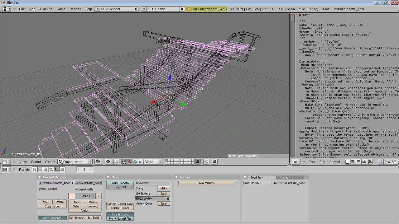
Importing ASE Models Into A 3D Application
So long as your 3D modeller of choice can import ASE models directly (native support or by third party scripts or tools) there shouldn’t be any problems bringing the mesh in ‘as is’. If not, an extra step will be needed requiring the object to be converted again into a format that can be used; Q3map2 only converts brushwork to ASE models.
There are a couple of points that need to be kept in mind when bringing in converted models of this nature – in essence the only useful data that’s brought in like this is the vertex and polygon face information, UVW’s are kept but they’re not really useful from the point of a model;
-
‘Planar’ UVW unwrapped
The UVW mapping applied to the faces of what were brushes is optimised for brush objects and not models; essentially a ‘flat’, ‘face on’ projection is used – brushes are UVW mapped as individual units and as such it’s often the case that although a texture may visually tile correctly over a group of faces it’s not necessarily the case that the actual mapped UVW’s will be doing the same thing and form a contiguous selection of UVW’d polygons.
-
Triangulated mesh
Because the compile process by default breaks brush data down into triangular polygons it means that converted models produced via this method are imported in the same state; they are composed of triangles rather than quadrangles (which is preferable for modeling).
-
Un-merged vertex points
Brush faces by default aren’t merged together to form a contiguous mesh, this means that each triangular polygon and it’s three corner vertices are separate objects from their immediate neighbours.
-
Missing textures
More often than not a mesh, although UVW mapped, will import into a 3D program without textures because of the way texture and shader paths are written to the ase file.
-
Individual faces
As with un-merged vertices above, by default triangular polygon faces are not connected together, instead they are individual objects and need reconnecting in your 3D application.
-
Models relative position
As mentioned above, a models position in a 3D application’s viewport is relative to where it’s placed in Radiant before exporting, maps sections can be built and exported in situ where required and re-centred in the 3D app before re-export back out to ASE.
Most 3D applications will have some method of merging vertices together and converting triangular faces into quadratic polygons, it’s a good idea to do this where available to ease the modelling process. Once this has been done the mesh can be edited and then re-exported to ase once work has finished.

Front view of brushwork in a caulk box
[1: Converting Brushwork | 2: Additional Options]

