Basic Patch Mesh Terrain & Subdivisions In (Qe)Radiant
Not all terrain needs to be complex modelled work. Using the patch mesh objects available in QuakeEdit (Radiant) means the level designer is able to make quick but basic terrain meshes using the limited functionality presented by patch meshes.
The following tutorial explains how to use simple patch mesh objects in Radiant to make basic terrains. You do need a basic understanding of the Radiant level editor and how to manipulate patch mesh objects to be able to make full use of the concepts discussed below. For a better understanding of this read through ‘how to.. patch mesh’.
Make A Simple Terrain In QeRadiant
There are basically two approaches to creating what is generally regarded as a ‘terrain’ in Doom 3 and Quake 4; the basic – using editor tools; the advanced – using external 3rd party applications to ‘model’ a 3D object. This following tutorial covers the former technique way; using patch meshes to create a basic terrain surface.
Design note: There was a third way to create a terrain – a trisouped brush mesh – but you can no longer get trouble free decent looking terrain objects using that old Quake 3 method (see below).
Tri-Souping In The Doom 3/Quake 4 Engine
Although Doom 3 and Quake 4 are essentially the same from a constructional point of view – i.e. how you build a level – as previous games powered by the Quake 3 engine, it has introduced a few ‘intolerance’s’ into the mix that must be taken into consideration. Relative to the context of this tutorial that means you can no longer build a terrain using a tri-souped mesh of brushwork (using ‘TerraGen’ or Gensurf’), if you do attempt to do this you’ll find broken brushes and cracks and gaps that, no matter how often you ‘tweak the verts’, simply can’t be removed.
Then there’s texturing. The Doom 3 editor (D3Ed) treats each face of a brush almost like a unique object, so unlike what you could do with previous versions, selecting a number of faces and applying a texture to them doesn’t by default result in evenly textured group of faces; each faces ends up with the texture rotated relative to the angle or orientation the face has. The result of this is that two faces sat next to each other won’t match up if they’re at angles to each other.
With this in mind it basically means you can no longer create an interesting terrain from a trisouped block of brushwork; it has to be either constructed from patch mesh objects or 3D models (the terrain is treated in the same way as mapobjects).
Using Patches, Keep These Rules In Mind
Although the basic principal is pretty straight forward; you create a brush, convert to patch mesh, texture, position and re-size the object – using them does require a few considerations which are all related to each other in one way or another;
- You’re not really going to be able to do anything overly complex : you can only really create ‘height based’ terrain, terrain that undulates like hills (or ‘boobs’ as many call them).
- A patch mesh isn’t ‘optimised’ : you can’t remove polygons that don’t ‘do’ anything. Whilst on an individual level this isn’t too important, on bigger mesh or where you have lots going on, that waste starts to add up in terms of it’s effect on the FPS.
- You can’t ‘blend’ textures : meshes can’t be ‘vertex painted’ which Doom 3 requires for that texture blending to work.
- Using mesh often means using more polygons than is necessary.
- Patches no longer use LOD (level of detail) optimising as was present in the last Quake 3 generation of games : patch mesh always stay at the resolution they were created with, they don’t ‘reduce’ as you move further away from them.
- You can’t control the ‘flip’ of a polygon.
Most of these limitations can be worked around to a certain extent but obviously using meshes won’t be nearly as versatile and controllable as modelling a terrain. On the other hand, it’s simple to use and with a little thought about what’s going on you can get some interesting results.
Patch Mesh Sub-Division Control
As mentioned above we’re creating terrain using patch mesh objects but because by default a mesh tends to have a high subdivision – the ‘cellular’ rows and column ratio – we need to find a way to gain more control over that and reduce the numbers being used.

A ‘simple patch mesh’ created with an 11×11 control point grid – blue lines indicate the main control grid composed and manipulated through a series of grid point (vertices), green lines indicating the location of edge subdivision in the patch mesh. The density of both depends in Surface Inspector properties
If you create a mesh like the one shown above – a patch mesh object using an 11×11 control grid – for each control point there is a polygon ‘strip’ division (represented by the blue lines; 11×11) with another ‘subdivision’ in-between the points (represented by green lines; 10×10). That’s a mesh object using 20×20 quadratic polygons (400 in total) which translates to 800 triangles. That’s a lot of triangles…!
Design note: see the tutorial DOOM 3 – getting custom models into Doom 3 for more information about the difference between ‘Quads’ and ‘Tris’ based polygons.
Fortunately there is now a tool that can be used to reduce or increase the patch mesh subdivisions, unfortunately it can only be applied to the whole mesh object, you can’t ‘selectively’ reduce polygons.
Reducing Patch Mesh Sub-Divisions
Simply select the mesh object and hit the ‘S‘ key to bring up the Surface Inspector (usually this is where you edit alter UV tiling information for textures so quite what a patch mesh control option is doing in here is anyone’s guess!). Once opened you’ll see an area in the bottom left that contains two sliders marked ‘horizontal’ and ‘vertical’ along with a couple of text input boxes (see image below).

Accessing the "Surface Inspector" allows the density and subdivision of a patch mesh to be changed using the "Subdivide Patch" option (checkbox needs to be selected for the option to take affect)
With the patch mesh object selected just turn on the Subdivide Patch feature by clicking the check box (as shown above) and then either slide the indicator or enter in a number to set the subdivisions; the number you use will depend on two things;
- The number of control points on the original mesh.
- The density of subdivisions required.
What you should be aiming for is a 1:1 ratio; that is, one polygon between one set of 4 corner control points, this tends to works well with larger mesh objects. The 1st image below shows the 11×11 mesh in it’s 1:2 ratio default state; the blue lines represent the control points; the green lines represent the subdivisions; the red line represents the physical orientation of the polygon edges.

Default subdivisions vary depending on the control grid resolution – shown above, the patch mesh has a relatively high subdivision density; N.B. the edges indicating each division tends to become visible only when shaped – if the surface remain ‘planar’ the mesh may appear as a simple single quad

Using the Surface Inspector to set the number of subdivision

When not activated mesh is not physically subdivided in the same way
This next image below shows the mesh after it’s had the subdivisions reduced to a 1:1 ratio; there are now no green lines which represented the subdivisions mentioned above.

Using smaller subdivision forces a 1:1 relationship to the control grid so the patch mesh reduces its polycount, loosing some structural detail as a result

Use “Patch Density” when initially making the mesh to set the number of control point required
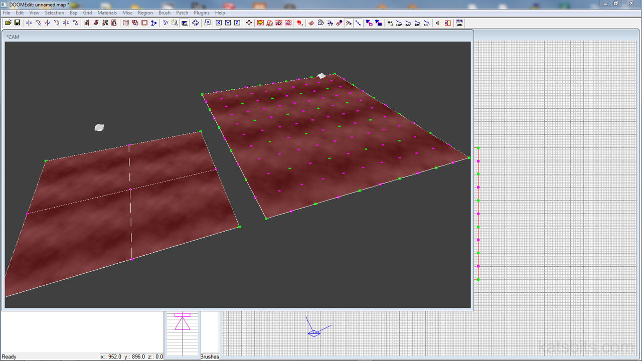
The in editor render below shows the difference between the two versions of the mesh. The one highlighted red is the default subdivided version. As can be seen here, the additional polygons of the higher subdivided mesh don’t really make all that much difference to the shape of the terrain and as a result can be regarded as wasteful and unnecessary; the reason the mesh was reduced in the 1st place.

Camera view in ‘Render’ mode showing both a high and low subdivided version of the same mesh and the difference in structure between the two – whilst using more polygons provides better shape, the over all impression in not that different or noticeable to the low polygon version
Think Of It Another Way
By reducing a mesh in this manner it does two essential things;
- Basic ‘optimising‘ of the on screen ‘tris’ (triangle) count by removing wasteful (‘dead’) polygons – which is actually a lot better than leaving the mesh in it’s raw state.
- Effectively a pseudo ‘Terrain‘ tool. With the polygon subdivisions on a 1:1 ratio with the control points you’re actually creating a ‘terrain’ tool that can replace the tradition terrain generators like Terragen or Gensurf; the control points of the patch mesh act in the same way as the heightmap tools that allow you to push and pull ‘verts’ up and down to create interesting features in the same way you would with a terrain generator.
If you think about a reduced patch mesh in the context of TerraGen et-al then you get a better idea of what you’ve got; a simple to use ‘terrain tool’ that has the ability to edit the mesh on a point by point basis. So basically that’s it, creating a terrain based on patch mesh work is pretty straight forward, the ‘thing’ you have to really watch out for is optimising the subdivisions, especially if you go on to do a medium to larger sized terrain map object. Next, adding other objects to the scene will be discussed.
