Make IMVU Furniture Using Nodes
With the introduction to IMVU of the ability to import FBX files, the process of making furniture items with or without pose spots has been made much more user friendly as now, instead of the complications associated with Armatures and Bones, primitive "Empty" objects can be used to represent the same hierarchy as ‘nodes’ that are much easier to manage and use. The following describes the basics of using nodes and how they work.
Download: Katsbits IMVU Furniture Example (c. 600 KB | *.blend, *.fbx, *.jpg, *.png).
The following material does not discuss making the game model/mesh seen in IMVU, i.e. ‘chair’, ‘lamp’, ‘bed’ or other visual element Users actually see in game/client. To learn how to mesh and make model in Blender click here.
Introduction
In Blender Nodes differ from Armatures and Bones in that their use does not create any hierarchical structures between objects, a group of nodes added a Scene is simply that, a collection of independent elements. Bones on the other hand, can only be added as part of an ‘Armature’ super-structure, which both contains and determines each bones relationship with others in the group.
Design note: bones cannot be added to the Scene independently of an ‘Armature’ Object. It is possible to add an Armature with a single bone however, so a group of bone would in fact be a collection of Armatures, each with one bone.

The FBX import process for IMVU now means Blender users are able to make furniture items using ‘nodes’, represented by "Empty" objects…

… when previously this would have meant using Armatures and Bones. Of the two nodes are much easier to use and export
What Are ‘Nodes’
In Blender, ‘nodes’ are "Empty" Objects, added to the Scene from 3DView "Add" menu – "Add » Empty » [type]", or by pressing "Shift+A" to access the "Add" pop-up menu. They are essentially reference objects indicating a point in 3D space that can be visualised using various pseudo-primitive shapes, "Cube", "Sphere", "Arrows" and so on. They are always drawn as ‘wire’ objects, an outline describing the selected primitive, e.g., "Cube" would be drawn as a ‘wire’ or outline in the shape of a uniform box. Empties don’t carry any significant value their immediate coordinates and orientation (position), and their "Size" (set in "Object Data" Properties), or if displayed using the "Image" option, a set of "Texture" and "Image" material properties. To be useful then, functional value, or purpose, is generally added after-the-fact, typically by linking Nodes to other objects in such ways as to mimic a given structure or relationship hierarchy.
Design note: aside from wireframe or outline display, Empty objects have fixed Origin points that generally sit centre of mass (exceptions are for "Arrow" and other ‘directional’ indicators), which cannot be moved or changed as is possible with other Object types (there is no option to "Set Origin" for example).

Nodes in Blender are "Empty" objects. They have no inherent properties other than size (available in "Object Data") and location and/or rotational position within the Scene. Their Origin points are conveniently locked to centre-of-mass, useful for ‘node’ functionality
Furniture ‘Root’ Node
For animated and non-animated ‘wall‘, ‘floor‘ or ‘ceiling‘ furniture products alike, the master or control element of the item is its "Root" node. It sits at the very top of the objects hierarchy. This means everything related to the item, the mesh, pose spots etc., is linked to it in some way directly, or indirectly through other nodes (cf. animated furniture). Once in IMVU the node is also used to determine the furniture location, rotation and orientation based on its placement in a room. This makes the nodes position and orientation within a furniture items structure import as it’s this node that determines whether an item appears to stand on a floor or hangs from a wall or ceiling surface.
Design note: in suitably set-up furniture rooms, and depending in the Root nodes orientation, furniture items can be mounted relative to wall, floor or ceiling surfaces.
As the Root nodes Origin is centre-mass it should be positioned so this point sits on, and is rotated axial to, grid-centre to ensure subsequent FBX export is correct relative to IMVU. To do this, in the 3DView right-click the large node named "Root" then in "Object Data" properties (the ‘Cube’ icon) set the "X", "Y" and "Z" values for "Location:" to "0.00000", and for "Rotation:" to "0" – in both instances left-click the input field and type "0". Press "Enter" confirming each in turn. This will orientate the node so it essentially faces front with its "Z" axis pointing up and "X" out to the side, important for furniture to display properly in IMVU.
Design note: due to the scale of IMVU items the nodes name may not be immediately discernable in the 3D View, if this is the case use the "Outliner" Editor to select it – with the Outliner visible left-clicking the entry titled "Root", the object will highlight in the 3DView. Once selected individual nodes can also be moved to the 3D Cursors location using "Snap", "Shift+S", and "Snap Selection to Cursor" ("Object » Snap » Snap Selection to Cursor" or "Shift+S » Snap Selection to Cursor"). To ensure furniture functions correctly in IMVU, the node when selected will show the "Transform Widget" (using "Global" orientation) so "Z" (blue) points up, "Y" (green) to points backwards and "X" points to scene left (Users right looking at the screen).

The master or control node of all furniture items is "Root" (case sensitive name). In Blender this is a simple "Empty" that should be centred on the grid – blue ("Z") widget arrow pointing up for floor furniture, inwards for wall and down for ceiling – reset the "Location:" and "Rotation:" properties in "Object Data" to zero ("0")

The Outliner Editor showing the basic structure of a simple furniture items with pose spots, everything is linked (via "Parent") to the "Root" node, including the mesh Users see in IMVU (set up correctly, "Root" should sit at the very top of the items hierarchy)
Pose nodes (Sitting, Standing & Custom pose spots)
Pose spots are where the avatars appear relative to room, furniture items or each other. A functional spot needs four nodes; a ‘handle‘ position which appears in IMVU as the spot Users click, a ‘seat‘ position where the avatar is actually located, and an interactive ‘catcher’ and ‘pitcher’ pairing for actions two avatars can perform together. For a standard seated poses these are;
- Handle[n]
- seat[n].Sitting
- Catcher[n].Sitting
- Pitcher[n].Sitting
For a standard standing pose these are;
- Handle[n]
- seat[n].Standing
- Catcher[n].Standing
- Pitcher[n].Standing
And for custom poses;
- Handle[n]
- seat[n].[custom_pose_name]
- Catcher[n].Standing
- Pitcher[n].Standing
Although the name for standard .Sitting and .Standing pose spots is fixed, they do carry a sequentially numbered identifier or reference IMVU then uses to determine their respective order of importance should more than one pose spot is included as part of a furniture item. In other words, if the nodes outlined above were part of a furniture item the first set would be ID’d as "01" ("seat01.Sitting" etc.), the second set "02" ("seat02.Standing" etc.) and the third "03" ("seat03.[custom_pose]" etc.). This lets IMVU know how many pose spots there are, and their priority (where the avatar appears first).
Design note: in the above "[n]" is a placeholder for numerical identifiers, starting at "01" through to "09", then "10" onwards. When using custom pose spots, or setting up a set of node for use with a custom pose, the name given to the seat node, i.e. "seat[n].[custom_pose_name]", is matched to an Avatar "action" pose ("Action" is not to be confused with Blenders "Action Editor"). For example an Avatar pose called "slouch" would mean "seat[n].Slouch" being the nodes name, which might then be matched in Create Mode to a pose triggered using "stance.Slouch" that holds an appropriate "Skeleton Animation" attributed to an action ensemble.
Important: node names are cAsE sEnsItIVe
When pose spots are included as part of a furniture item their nodes are all linked to the furniture’s "Root" node using "Parent". This creates the necessary hierarchical structure IMVU needs for functioning items. In Object mode multi-select ("Shift+RMB") all nodes, selecting "Root" last. From the 3DView’s "Object" menu select "Parent » Object" and then "Object (Keep Transform)" in the pop-up that appears. A dashed link will appear between "Child" (pose nodes) and "Parent" (Root node) indicating a relationship.
Design note: make sure to use "Object (Keep Transform)" when parenting pose spot nodes to other nodes (Root or otherwise) to ensure the location and rotation coordinates are kept, otherwise the nodes reset when linked. If this happen use "Ctrl+Z" to undo the action.

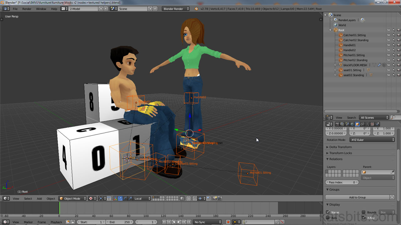
The nodes used for a standard ‘sitting’ avatar pose spot – "Handle[n]", "seat[n].Sitting", "Catcher[n].Sitting" and "Pitcher[n].Sitting" (mesh dummy also shown)

The nodes used for a standard ‘standing’ pose spot – "Handle[n]", "seat[n].Standing", "Catcher[n].Standing" and "Pitcher[n].Standing" (mesh dummy also shown)

The nodes associated with pose spots can be positioned and then linked to the furniture’s ‘Root’ node using "Parent" – select all nodes, Root last, then from the 3DViews’ "Object" menu select "Parent » Object » Object (Keep Transform)" (selection order is important, "Root" last)
Furniture Mesh
The furniture mesh is the object Users see in IMVU, it doesn’t do anything beyond being a visual, all the actual mechanics attributed to avatar interaction is performed through the underlying node structure. With that said meshes do need some basic preparation before use so they behave correctly in IMVU; at least one Material needs to be assigned to the mesh, which also needs to be UV unwrapped and itself assigned an image (bitmap), this being associated with the Material.
Design note: Material names should be appended a sequential numerical reference as the FBX import process uses the indices to establish the items structure and material/texture assignments once imported into Create Mode, e.g. "table [0]", "legs [1]", "cloth [2]". This means it’s possible to use the same reference differentiated with the numerical append, e.g., "block [0]", "block [1]", "block [2]" etc. For more on using Materials in Blender click here, and UV unwrapping meshes in Blender click here.

Shown in "Solid" mode for clarity, when assigning materials to meshes, although any descriptive words can be used for ease of recognition, each reference should have a numerical append, "[materialname]{space}[n[" ("materialname [n]"), to ensure the FBX export » import process reassembles the item correctly in Create Mode

Most important for meshes is that they have a "Vertex Group" assignment that matches the underlying node structure. For simple objects this generally means creating a groups named "Root" to mirror the Root node.
Design note: the groups and the names mirroring the underlying node structure is what IMVU uses to actively link the different element together so items behave correctly when manipulated by the User.
In Edit Mode press "A" to "Select All" highlighting the entire structure. Then in "Object Data" properties (inverted triangle icon) left-click the "+" (plus) button to the right of the "Vertex Groups" section aperture. A new listing appears named "Group". Double left-click to highlight for editing and type "Root". Press "Enter" to confirm then left-click the "Assign" button below to assign the new group to the mesh selection. Exit Edit Mode and "Parent" the mesh to the Root node; multi-select the mesh then Root Node (selection order is important), then from the 3DViews’ "Object" menu click "Parent » Object » Object (Keep Transform)".
Design note: to test vertex group assignment use the "Select" and "Deselect" buttons, if set up correctly the mesh will clear and highlight when the respective button is clicked. Similarly to test the mesh being properly parented to the furniture node, once link right-click the Root node, press "G" and ‘move’ the selection, if set up correctly the mesh will move with the node. When ‘parenting’, i.e. creating a meaningful ink between mesh and controlling node, the "Armature" Modifier can’t be used because the property doesn’t recognise the "Empty" object used as the Root node being a valid ‘armature’ elements; parenting has to be performed using ‘Object (Keep Transform)’

For furniture items to work properly in IMVU meshes must have at least one "vertex group" named "Root" – once parented to the Root node, this group is what links the two functionally together so they can be moved and manipulated as a unit

Furniture meshes typically need at least one "Material" with a "Texture" and "Image" slot, the latter then being mapped to the UV’s of the object once unwrapped

Optionally, meshes can also be vertex painted – select the mesh then switch "Interaction Mode" to "Vertex Paint", or press "V" (mesh shown tinted with vertex painting, adding basic shading to the object); using the ‘Paint’ tools in the Tool Shelf, paint individual vertices to add colour or tinting
Animating Furniture Nodes
Adding optional animation to node based furniture is as simple as selecting the node to be animated and ‘keying’ its movement over a series of ‘frames’ as a sequence in the "Action Editor".
Design note: key frames should only contains ‘location’ and ‘rotation’ data, ‘scale’ isn’t usable in IMVU (typically this might be done using Shape Keys).
In the 3DView right-click select the node to be animated. Switch the "Timeline" to "Dope Sheet" (click the "Current Editor type…" button, select "Dope Sheet") then left-click the "Editing context to be displayed" selector and click "Action Editor". If the green timeline widget/slider is not at frame "1", left-click drag it into place (or left-click drag) then press "I" to "Insert" a key frame for the nodes current (start) position, selecting "LocRot" from the "Insert Keyframe Menu" pop-up. An orange marker appears in the timeline. Advance the green frame widget to another frame, move or rotate the node to another position in the 3DView and press "I" again to mark another "LocRot" keyframe. Advance along the timeline as required, repeating the process until the sequence is complete. To confirm ‘scrubbing’ (left-click dragging) the green timeline widget/slider back and forth will play through the sequence.
Design note: to accommodate animation the node structure of the item may need to be changed – where possible avoid animating "Root" and instead add extra nodes that cater specifically to being animated that are themselves then parented to Root. Weight paint or vertex group any section of the mesh that needs to move as part of the animation to this new node (rename a preexisting group or create new ones as needed). Any pose spots that also need to accompany the animation should be parented to the new node not Root.

An extra node added to accommodate animation, its position and rotation is marked to the "Action Editor" to create a animated sequence that can be exported to FBX – select the node, press "I" to "Insert" a keyframe, select "LocRot" from the available options

The animated node needs to be parented to "Root" with other associated nodes being parented to the animated node, pose spots for example. The mesh also needs a vertex group (be weight painted) to the animated mode to is moves with the sequence
Export Furniture To FBX
With nodes once everything is parented to "Root" the item is ready to export to FBX, simply multi-select ("Shift+RMB") the nodes and mesh, making sure to select "Root" last (important). Then from the "File" menu select "Export » FBX (.fbx)". Blender will switch to the "File Browser".
Design note: the available FBX export options may differ from those shown based on the version of Blender being used (the FBX export script differs across versions).
Here change the file name and save location as needed then in "Export FBX" options lower-left, under "Main" activate (select) "Selected Objects" and in "Armatures" deactivate (deselect) "Add Leaf Bones". Leave the remaining settings as they are and left-click the "Export FBX" button top-right. Blender will parse the file, including any animated "Actions", saving a *.fbx file to the selected location ready for import into IMVU.
Design note: from an FBX export point of view, Root being selected last ensures the process uses that item as the local origin for the overall item as a group of linked objects (which is also why it should be zeroed on Blenders grid). When imported into IMVU if an unexpected set of extra set "*_end" bones appear, this is the result of "Add Leaf Bones" being selected. Make sure this is disabled on export from Blender. When exporting "Shape Keys" (‘morphs’) disable "Apply Modifiers" in "Geometries" to ensure sequences are not destroyed during export – this may require applying any modifiers in Blender prior to export to ensure the mesh is correctly exported.

When exporting for FBX select the Root node last to ensure it is used as the local origin point for the item as a group. To export from "File" select "Export » FBX (.fbx)"

In the "File Browser" that appears on exporting, activate "Selected Objects" under "Main" (note options may differ depending upon the version of Blender used, the script varies accordingly)…
")
… and disable "Add Leaf Bones" in "Armatures". All other settings can remain as they are before then clicking the "Export FBX" button top-right
Summary
The following is a summary/checklist of the preparation and export of node based furniture for IMVU using FBX export/import (includes simple node and mesh furniture, and node, mesh and pose spot furniture).
- Nodes
- The Parent and Origin of the furniture item must be named "Root" (upper-case "R"). It should be centred on Blenders grid with "Location" and "Rotation" values set to "0" UNLESS its a WALL or CEILING item (rotate "X" to "90°" and "180°" in "Object Data" respectively).
- All remaining nodes must be "Child" nodes of Root (Root is their "Parent").
- When Parenting use "Object (Keep Transform)" to maintain nodes location and rotation coordinates/positions.
- Additional nodes can be given arbitrary names but must be parented to Root.
- Nodes used for Pose Spots must be numerically identified in sequence where more than one set is used ("seat01.*", "seat02.*" etc.).
- Names for custom pose spots should mirror the avatar action (not to be confused with Blenders Action Editor or ‘Action’) to be assigned in Create mode.
- Distance between nodes is crucial, avoid adjusting (click here for more).
- Node are ‘fixed forms’ so "Apply" is not necessary.
- Node names are cAse SeNsiTive.
- Mesh
- Mesh needs at least one "Material" with a "Texture" and "Image" slot assigned and properly sequentially identified ("(name) [0]", "(name) [1]" etc.).
- Mesh needs to be fully UV unwrapped with an Image (bitmap) assigned (typically the same image assigned to the Material).
- At least one Vertex Group is required named "Root".
- Before Parenting use "Apply" to reset the mesh.
- Mesh Origin should be positioned at grid-centre in Blender – subject to its positioning relative to its use as an item in IMVU (e.g. offset to allow placement against wall).
- When Parenting select the mesh BEFORE Root, the mesh is a "Child" of "Root".
- Optionally vertex painting can be used to tint the mesh.
- Export
- To export left-click "File » Export » FBX (.fbx)".
- In the "File Browser", amend the file name and save location.
- In "Export FBX" options (bottom-left);
- Ensure "Version:" is set to "FBX 7.4 binary".
- Set "Scale:" to "1.00".
- Enable "Selected Objects" under "Main".
- Disable "Add Leaf Bones" in "Armatures".
- Leave other settings as is (disable "Apply Modifiers" if exporting "Shape Keys").
- Click "Export FBX" top-right.
Furniture Node Video
Overview of the node based furniture item set up and export to FBX from Blender – simple node based furniture and node based furniture including pose spots.
[Duration c3 mins] exporting a simple node based furniture item from Blender using FBX (for IMVU)
[Duration c3 mins] exporting a simple node based furniture item including pose spots from Blender using FBX (for IMVU)
[Duration c.3 mins] adding animation to node-based IMVU furniture items in Blender

