How NOT To Make Normal Maps From Photos Or Images
Although normal maps (or ‘local maps’ to give them their Doom 3 name) ideally should be generated by rendering an incredibly high resolution three dimensional object into 2D, this approach may be seen as being over the top for the more casual mapper or texture artist who just want to enjoy creating new texture assets for Doom 3 or other ‘next Gen’ games without the need to go ‘hardcore’ and learn a 3D application. If you’re one of these chaps then this ‘tutorial’ is for you.
Having said that, this tutorial isn’t a step-by-step guide – a "how to make a normal map" run through as it assumes you have at least a basic understanding of the photo editing application you have access to in order to create the objects required for the bump map process. It’s not a technical thesis nor is it about passing photographs through the various filters either, you don’t need instructions on how to do that; in fact, this tutorial will highlight why you shouldn’t do that, or at the very least why you don’t get the results you’d expect from photographs.
What you’ll see outlined below is the best method currently available for producing normal maps from 2D art work, highlighting the things you should be aware of as you work and along the way helping you to understand what the various tools and utilities are actually doing in the process.
The Basics Of Making Normal Maps
The basic process is to use a grey scale image, created specifically for this purpose – to create a normal map – and pass that through either the ATI tga2dot3 stand alone tool, the nVidia photoshop, the ‘Gimp’ plug-in or any other 3rd party normal map generator). Each of these app’s basically converts the grey scale image into the equivalent DOT3 colour counterpart. Depending on which tool is used varying amounts of control can be had over the resulting normal map in terms of how strong the bump effect is.
Normal Mapping A Photo Of A Door
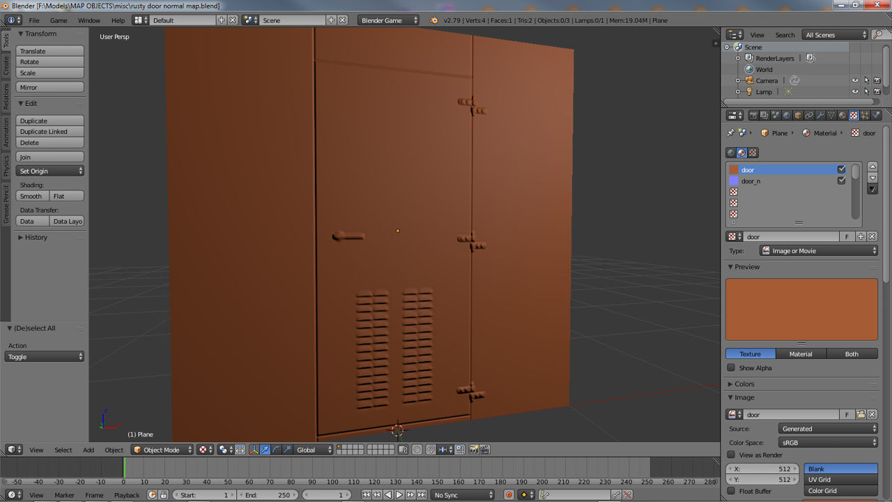
What we’re going to be creating is a door similar to the photograph opposite. The easiest thing to do would be to convert the photograph to grey scale and then pass that through one of the bump tools to get a pretty quick normal map There is a problem with doing this; the tools can’t really get any ‘genuine’ height information from the image other than the very obvious stuff – the gap in the door and shadows caused by the presence of the hinges and so on. It doesn’t matter how much you alter the ’emboss’ height values in the bump tools interface, you simply can’t get ‘clean’ height information from the photograph so the end result in game is not particularly good; it’s essentially all ‘surface’ and no ‘depth’. By doing this all that’s basically happened to the image is that it’s been embossed because although ‘we’ can tell what the image is and what it’s supposed to look, the tools can’t.
Design note: it’s worth pointing out here that the tools are effectively ’embossing’ the image in exactly the same way you would normally do to any type of image if you wanted to create the illusion of ‘faked’ depth (like a beveled edge). The only real difference is the output, it’s colour orientation is ‘normalised’ (Red, Green, Blue).
This is in essence where the problem lies; not the emboss aspect, but instead how ‘literal’ the tools are being in their interpretation of the tone and colour values interpreted from the image (we’re in grey scale don’t forget). Whilst we can look at that image and ‘see’ the three dimensionality of the objects and fittings because we know what they’re supposed to look like (which for us is helped by of the play of light and shadow on the objects), the tools can’t, they have no way of making that distinction. All they know is ‘black’ creates depth and ‘white’ creates height, giving 256 tonal differences between the two.

Photograph of a ‘real’ door that looks interesting enough to create as a normal map
Filtering Photographs
It’s important to understand what the tools are doing in relation to the images you pass through them, once you understand this you understand why you can never get the result you think you should get from an unprocessed photograph passed through them. Essentially the information a photograph contains is ‘incorrect’ for the tools to use, we use ‘black’ for any number of visual interpretations of any given scene, the tools only understand ‘black’ as signifying ‘depth’ relative to neighbouring colour or tone.
As an example look at that image above again and take note of two areas; the ventilation grills and the hinges. It’s easy to spot the shadow on the hinges, which for us emphasise the height of the metalwork. But if you look at it again and note the colour tones of the hinge, although darker they’re not strikingly different to the tones of the rest of metalwork around them. The normal map tools see this slight tonal difference and the ‘black’ of shadow and it interprets literally by pushing those areas back into the normal map, it doesn’t see it as ‘shadow‘ but instead ‘depth’ and so it behaves accordingly.
The same happens to the vents. We can tell what they are and that they’re 3D based on the information we can see but look again at the colour and tones of the grill; again they’re slightly darker tonally than the rest of the metalwork around them which for us when combined with the other local tone and colour information give us ‘3D’ vents. As with above, the tools see that slightly darker tone as representing depth and as a result pushes the dark values back. In the case of the grill this creates a weird backwards emboss which confuses the image in terms of what we understand ourselves to be looking at; "that should be sticking forward shouldn’t it?".
This is why you always get very messy results from passing an unprocessed photo through the tools, they’re essentially being interpreted literally.
That’s a pretty extensive bit of background information that should helped clear up what’s going on and why you can never get the results you thought you’d get. Now that we know this information we can use it to our advantage in creating some interesting and detailed normal maps from images.
So The Normal Map Tools Do What?
The tools work with 24 bit images using grey scale values to represent height and depth information; black is as far back as you can go and white as far forward – place a blurred white spot on a black background and you create a normal map with a ‘bump’ on it. This means that if we use a ‘mid’ tone grey to represent ‘0’ height/depth, objects that require height (sticking up from a surface) need to have white or light tonal values in them somewhere; objects that sit below a surface need black.
With this in mind look at the image opposite; it’s called a heightTemplate and has been constructed specifically for the creation of a normal map using one of the bump map tools. It differs from the normal grey scale height maps because it doesn’t contain any surface ‘noise’ detailing – scratches, pot marks, etc. – the heightTemplate should only contain basic layout and height/depth information – a ‘block out’ of the physical attributes of the object in question – surface noise and fine details will be added later in game by the heightmap.

The grey scale ‘heightTemplate’ used to generate the normal map The original is 512×512.
Creating A ‘heightTemplates’?
Because we’re only having to deal with the basic information – the ‘what’ of an object (i.e. ‘what’ is it?) – the template doesn’t need to be too complex, it doesn’t need any surface information, just features similar to those found in the template image above – ventilation grill, door hinges and so on. It’s at this point that all the information mentioned above about how the bump tools behave comes into play; we now need to figure out how to create the correct sense of height in relation to how the bump map tools interpret those values.

The images opposite show both a template and the resulting bump map and how different types of ‘blur’ effect the out come of the normal map.
Stripped down to the bare essentials we’re now looking at objects as if lit from the top down using a single light source with no ‘traditional’ shadow information (no ‘cast’ shadows like the hinges in the photograph at the top of this article). Height is now defined by grey scale tonal values, the closer to white the higher it is; a cylindrical object for instance would have a ‘white’ centre section and ‘dark’ edges instead of the typical ’embossed’ highlights of light on one side and dark on the other that we’re used to seeing on ‘3D’. The image opposite for example shows a ‘cylinder’ object created by combining three individual component layers together to give a final ‘combined’ stage which is then passed through the bump map tools – the top half is the heightTemplate, the bottom the normal mapped results.
As you can probably see from this little test image attention does need to be paid to the blur values applied applied to objects, high blurs (high blur values) give smoother results to both the template and normal image but they often look flatter. Low blurs (low values) generally result harder images often showing strongly defined central areas (usually the centre point from which the blur effect ‘originates’).
Design note: it’s well worth doing a number of these little tests using an assortment of shapes and 2D objects of differing tonal values to get a feel for the process. Along side various blurs and other graphical ‘effects’ you’ll be able to better judge how the tools will behave generally before you start working on more complex 2D template objects.

The image above shows a template with various tones of grey (from black to white) and their resulting effect on the normal map. Notice the ‘body’ colour on the normal map (the areas which correspond to the tones on the template) is almost exactly the same for each one. This is almost irrespective of the tone or any expected colour change relative to the height template.
Continuing with these experiments to find out how the tool behave, the image on the left shows a normal map in relation to the grey scale values to create ‘height’ from the heightTemplate. We know that white is the highest point ‘up’ and black the lowest point ‘down’ but, as you can see from the image opposite, the results aren’t quite what we were expecting; the interpreted ‘height’ difference based on the tonal values doesn’t appear to being doing that much – there are difference between certain ones, but not others; why is this?
If you look at that image again you’ll notice something odd about the normal map, it’s quite clear looking at it that there aren’t any tonal differences between the normalised colours and the corresponding greyscale squares on the heightTemplate, surely they should be different tones of that purple-blue colour? Well, the answer to that is ‘no’ unfortunately, the normal maps used by Doom 3 don’t make use of height information (z-axis).
So just how are the bump map tools defining the respective areas of height if they don’t change the tonal colours of various areas? The answer? The edges around each object. Basically the bump map tools generate height information by ‘beveling’ or using an photo editing ’emboss’ like filter process to the greyscale tones it interprets from images, producing ‘height’ based on what’s there and the amount of space in which it can do it. Height is ‘inferred’ rather than ‘actual’. Obviously it can only use so many pixels around the edge of an object before that starts to interfere with the object itself and corrupt the results (this happens when you turn the bump value up when using the bump tools).
If you have a look in game at the textures you’ll notice that nearly all of them have been designed with slopes, gradients and other ‘angled’ faces on them which account of the fact that normal maps can’t read literal height information, this is what the grey scale heightmap is supposed to be for – the two being merged together at ‘runtime’ to get much better results than either on their own.
Templates, Normal Maps & Image Resolution
It means several things which result in something similar to the image opposite. The clarity of particular features included in a heightTemplate are resolution dependant; i.e. the larger the image is the better the quality of the end result; but and this is an important ‘but’ the larger you make your images, for the sake of clear artwork, the greater the performance hit and texture load (GFX/CPU overheads, map load times etc.) you’ll create for the game and PC to run larger assets.

Anti-aliasing may cause some odd results under certain situations because of the way the bump tools interpret the tones from the template. In the images above the mid-toned grey line could result in a ‘step’ on the local map rather than a ‘smooth’ height transition.
Don’t forget that in nearly all cases Doom 3 is loading in 4 times the amount of assets per scene than any Quake 3 powered game because it has to load in diffuse, specular, height and local (bump) maps; one 512×512 texture is using 4×256, so for every 1×512 set – 1x_d, 1x_s, 1x _h and 1x _local – you’re using 4×256 – 4x_d, 4x_s, 4x_h and 4x_local – that’s a lot of data in Doom 3.
You also have to keep an eye on anti-aliasing when working, especially at the smaller texture sizes; the one pixel mid toned grey strip along the left and top edge of the image above can potentially cause odd problems particularly where there are fine details are needed. Anti-aliasing or the reduced pixel information at smaller images sizes can cause anomalies in bump maps as well. A curve at 512×512 has far more information available for the bump map tools to use for interpreting that curve then the same curve object at 256×256 or indeed 128×128 as the case is with a good number of assets in Doom 3.
The depth of features like lines between paving slabs or the crack in a door is limited by resolution, the smaller the texture the less information there is for the bump map tools to generate any significant amount of depth or detail, so any areas that you’d want to be quite deep should have at least 3 pixels worth of depth information available, two ‘edge’ and one ‘grove’. Ideally the ‘grove’ should be tilted or angled as an extension of one of the edge pixels otherwise as was shown above, the flat height difference is ignored – titling the grove will force the bump tools into using a normalised colour that represents further depth than the edge pixels alone would do.
How Do I Create Objects Like A ‘Hinge’ That Need Hard Edges?
Depending on what you’re trying to do, by being aware of the potential pitfalls mentioned so far it’s possible to create just about any sort of localmap from a template image. The hardest shapes to get right are cylinders and objects based on that in part or in whole. The height difference created by the curve of a pipe or circular / cylindrical object may involve a fair bit of experimenting to get results relative to what the textured shape needs to look like in game.

Exploded view of the hinge from the height-Template shown above. It’s possible to see more clearly how the tonal differences and various draw ‘effects’ (like the sharp edges) work together to create curves and height differences relative to each ‘object’ and it’s surroundings.
For example the barrel cylinder shapes used for the hinges on our test door were created in a similar way to the first of the test images above by taking a ‘lozenge’ shaped object and blurring it so the edges faded out towards the edge; you can see the results of doing that opposite. Although not a huge difference in tone it’s enough for the bump map tools to create a nice curve. The are plenty of different ways to actually create the effect of a smooth blend but as mentioned above using a gausian blur is usually all you need to do. The barrels are then finalised by cutting off the ends of the cylinder to create a sharp edge on the template; this will be interpreted the same way by the bump tools – a sharp or hard edge. The ventilation grills were created in a similar way with a hard edge along the bottom of each individual ‘vent’ object on the template so the bump tools could pick that up correctly.
One of the other things you may have noticed in the image above is the tonal colour of the hinge plates; they’re part of the same object but slightly different tones. The reason for doing this to keep the height of the plates relative to their immediate surroundings; they basically don’t want to stick up from the surface they’re sitting on too far otherwise they’ll look ’embossed’ rather than ‘normal mapped’. Making them both the same tone would mean the normal mapped version would have the plates occupy the same plain (same height relative to each other) but at different heights to the backgrounds upon which they sit – the background on the right of the centre line is below the height of the door (on the left) so the hinge plate would appear to be made from ‘thicker’ metal – the normal map would give a thicker edge to represent this because of what was mentioned previously about how the process creates ‘height’.
Design note: it might be worth playing around a bit at this point creating a series of test images using different blurs, fades, effects and basic shapes and then passing that through the bump map tools to get an idea how each ‘type’ of object behaves. Do this a couple of times and you’ll begin to see what the bump map tools are doing and so allow you to adjust what you do on the template to suit the needs of the eventual localmap image.
Comparing Normal Maps
The two images in the following sections below show the normal maps generated from the heightTemplate (the first one) and the original photo (the second one), both passed through the nVidia photoshop plug-in with the same settings, both the same size (512×512 in this case) and both 24 bit RGB grey scale (composed of grey tonal values – this may mean having to convert a colour images into 8 bit grey scale so as to get the 256 grey scale tones and then back into 24bit – how you do this will depend on your photo editing software).
The first thing you notice is how ‘clean’ the first one is – generated from the template. The second – generated from the photo – has a lot of surface noise picked up from the photograph. Both basically have the same information about ‘what‘ the object is, but because the first contains only that information it allows for a much clearer normal map – it simply contains just the information needed to create the basic shapes required to describe the door and it’s component objects; the hinge, the door object itself, the vents, etc. There’s no real need for ‘noise’ detail on and object like this, that sort of surface detailing will be provided by the heightmap later on.

The normal map results from the heightTemplate
The photographic version has the same information in terms of ‘what’ the object is but because it also contains a lot of extraneous information due to the presence of ‘light’ and ‘dark’, the results are not nearly as ‘clean’, it’s simply far too ‘noisy’ (too much surface scatter).

The normal map results from just the photograph
When the two processes of using grey scale height images to produce normal maps are compared side by side like this we can now clearly see what’s going on; light and dark tones and colours don’t mean the same thing to the bump tools as they do in a photo, it’s that simple; tone and colour are processed relative to what the bump tools are trying to do – dark tones represent depth and are pushed ‘back’ into the normal map, whereas light tones represent height and are pushed ‘forwards’ out of the normal map. In the case of using our door photograph the tools produce a ‘confused’ image based on this ‘correct’ interpretation that’s basically no good as a normal map; any dark areas regardless as to whether that’s dark ‘dirt’, dark ‘stains’ or simply dark ‘shadows’ get processed the same way, as depth. The same goes for ‘light’ tones being processed as ‘height’.
Final Normal Mapped Results
The two images below show each normal map with a ‘diffuse’ layer over the top. For the normal map create from the photo, it’s the photo itself. The normal created from the heightTemplate uses a specific image created just for that purpose (see image at top of article). The difference in clarity between the two is pretty obvious and what you see here is what’s you’d see in game. The results should speak for themselves in terms of which method you use to create the image used to process the normal map.

The colour map applied over the normal map generated from the heightTemplate

The colour map applied over the normal map generated from the photograph
Footnotes
Reading the tutorial in relation to normal (parallax) map creation for Elder Scrolls : Oblivion and other none id software normal mapped games
Important: keep in mind that this article aims to discuss ‘normal’ and ‘parallax’ maps in relation to game engines, which often tend not to implement the technology fully or use terminology that’s not 100% technically correct – for instance, ‘proper’ parallax maps (i.e. maps that conform to technical papers on the subject) do something called ‘self occlusion’ which Oblivion’s parallax maps do not do. For more information on this search the Internet for technical papers covering the subject.
There’s little difference in ‘technique’ between the processes used to create artwork for any type of game that utilise normal maps to ‘fake’ rendered depth to the information presented in the tutorial above (which was originally written for games powered by id software technology). In other words, you can use the same process described above for any game and still have a working normal map at the end of the process. There are however, a couple of things that you must check;
- RGB orientation
- How the alpha channel is used (if any)
RGB Orientation
RGB orientation is quite important, if you get the colour channels (R – Red, G – Green, B – Blue) the wrong way around it’ll effect the appearance of the texture in game; it’ll be flipped or inverted. Getting this wrong won’t break the game it just means a bit more work to fix it, which thankfully it is relatively easy to do by simply flipping individual channels until the texture renders correctly in game.
How The Alpha Channel Is Used
Generally speaking most games and interactive 3D use an images alpha channel as a ‘mask’ of some kind, essentially telling the engine to use the 256 available tones between black at one end and white at the other (a "grey" image as it’s commonly referred) to do ‘something’ to the texture relative to the tonal black/white differences.
In the Doom 3 engine for instance, it’s used as an actual ‘mask’; it knocks out (removes) sections of the texture from being rendered. Other game engines most commonly it’s used as a ‘specular’ layer; the mask effects the ‘shininess” of the image in game – a worn metal plate for instance, might have shiny edges where it’s been held which, over time, will smooth out and become shiny.
Depending on the game, the mask layer could also be used for parallax mapping which means the same grey scaled tones effecting the increased depth that parallax mapping offers instead of specular highlights – Bethesda’s implementation of ‘parallax’ in Elder Scrolls : Oblivion does this for example, it uses the information held in the alpha channel of the diffuse image as ‘instructions’ to be interpreted by the games engine as ‘parallax’, boosting the effect of depth ascribed to what’s seen in game.
So, when creating content for games that use normal maps it’s important to check for the above two ‘features’ at least before anything is done, simply to save you the extra work of having to correct errors after it’s found that a batch of artwork is incorrectly set up or the wrong way around in game.
Normal Maps & Other Games
It’s important to note that the tutorial above mentions techniques and principles that are not mutually exclusive to games powered by id software’s Doom 3 engine (idtech 4); in other words, making a normal map for any game that supports it uses exactly the same process as used for Doom 3/Quake 4 content creation, usually only the RGB orientation is different (see above).
Making Textures For idtech 4 Powered Games
Because Quake 4, Quake Wars, Prey and others run on the Doom 3 engine (idtech 4) it means that everything to do with the texture creation process for Doom 3 applies directly to those games; that means you can use exactly the same height (bump) maps, normal maps, diffuse and specular maps in both Doom 3 and Quake 4. This also applies to the principles used when creating textures; anything you’ve already read about, either here at KatsBits, or elsewhere on the Internet, can be applied to texture making for both games.

